Apparatus and measuring method of aberration coefficient of scanning transmission electron microscope

a technology of aberration coefficient and scanning transmission electron microscope, which is applied in the direction of material analysis using wave/particle radiation, instruments, nuclear engineering, etc., can solve the problems of increasing adjustment time, general difficulty in specifying, and difficulty in setting slice levels, so as to achieve the effect of reducing adjustment tim

Inactive Publication Date: 2007-07-12
HITACHI HIGH-TECH CORP
View PDF1 Cites 50 Cited by
  • Summary
  • Abstract
  • Description
  • Claims
  • Application Information

AI Technical Summary

Benefits of technology

[0007] An object of the present invention is to eliminate the above prior art drawbacks and according to the invention, a Ronchigram is acquired using a spherical specimen, various kinds of aberration coefficients are measured from inner and outer diameters of a ring pattern appearing in the Ronchigram and a radius of the specimen as well and a spherical aberration corrector is adjusted on the basis of the measured coefficients. Thus, without resort to direct measurement of a line of infinity magnification which is difficult to specify from the Ronchigram, the aberration coefficients can be measured. Besides, through the use of the spherical specimen, the aberration coefficients can be measured from image data of a single Ronchigram. In this manner, the adjustment time can be shortened expectantly.

Problems solved by technology

The ring pattern appearing in the Ronchigram image and corresponding to the infinity magnification does not contrast with the neighborhood and is generally difficult to specify.
This raises a problem that the adjustment time is increased by time consumed for acquisition of the plural Ronchigrams.
For the same reason, it is also very difficult to set a slice level when the ring pattern is estimated through pixel operation.
Accordingly, specifying or identifying a pattern corresponding to the infinity magnification cannot help having resort to inaccurate measurement with the eye and eventually, gives rise to acquisition of mere aberration coefficient values containing errors.

Method used


Image

  • Apparatus and measuring method of aberration coefficient of scanning transmission electron microscope
  • Apparatus and measuring method of aberration coefficient of scanning transmission electron microscope
  • Apparatus and measuring method of aberration coefficient of scanning transmission electron microscope

Examples


embodiment 1

(Principle of Determining Aberration Coefficients from Ronchigram)

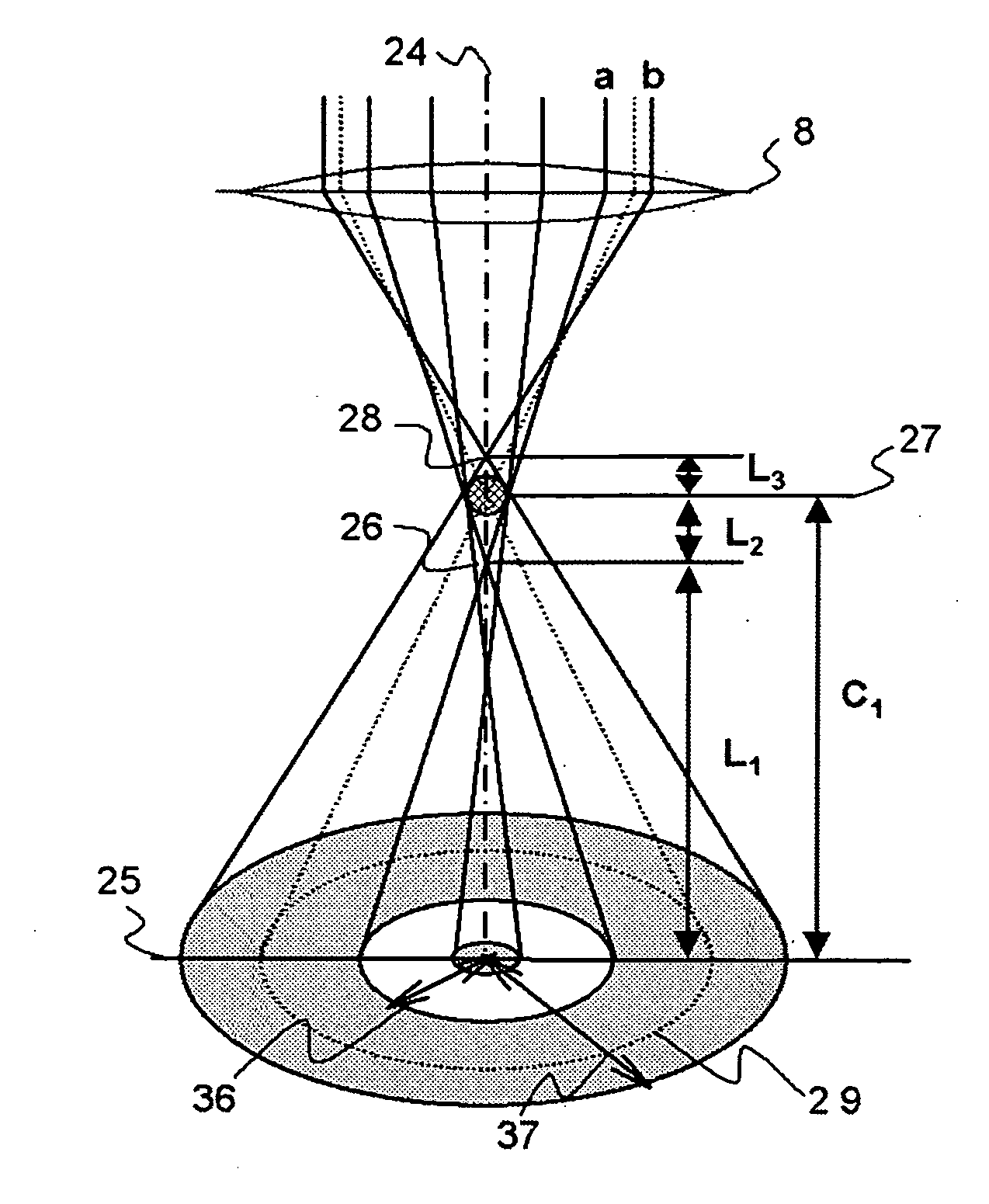
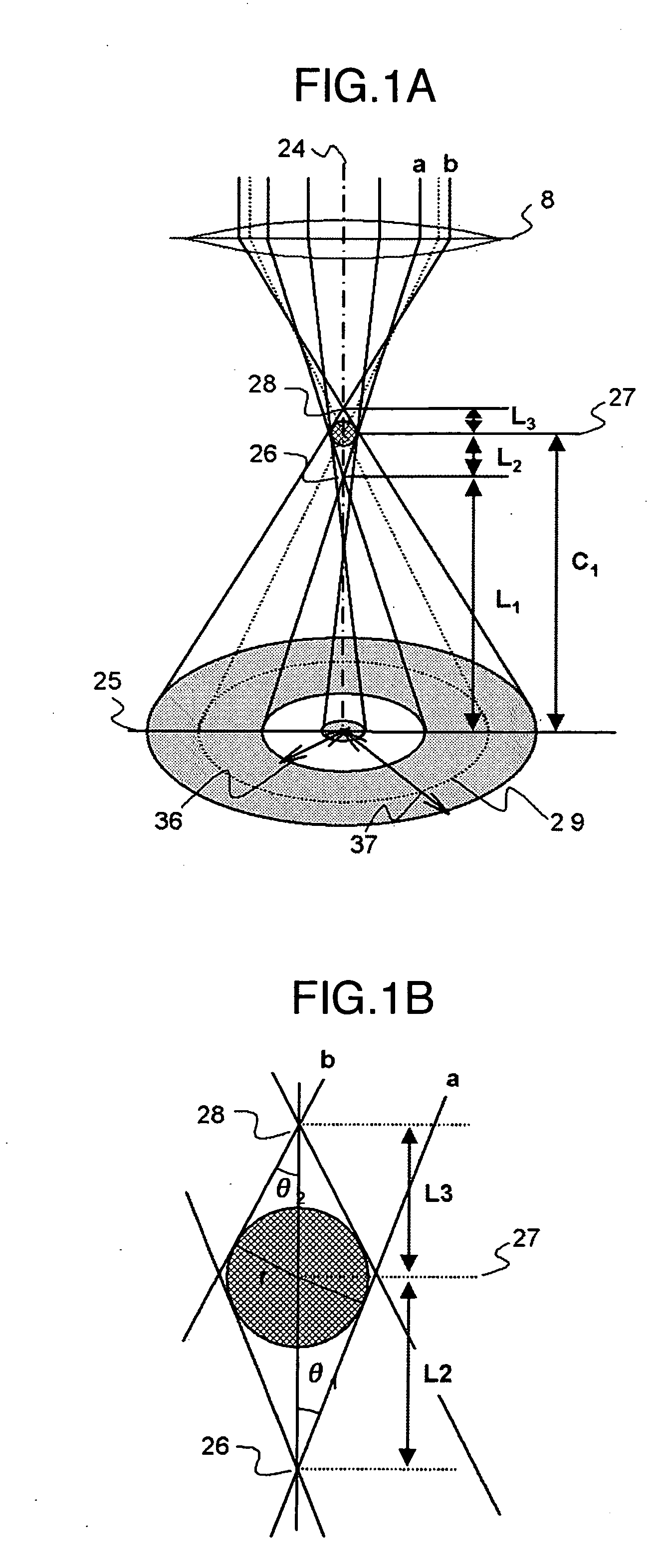
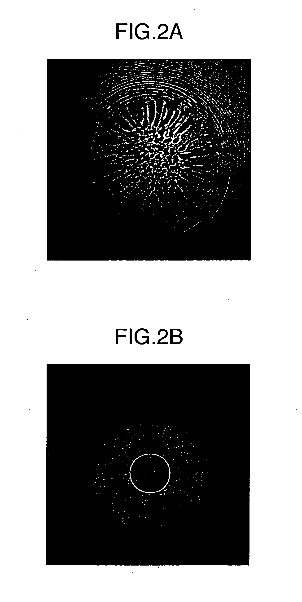
[0018] Referring first to FIGS. 1A and 1B, the principle of acquisition of a Ronchigram according to the present embodiment will be described. The Ronchigram is an image observed on the axis when scanning of an electron beam is stopped with the aperture released or an aperture of large hole diameter used and has a nature of susceptibly relecting an influence an aberration has upon the electron beam on the axis. Diagrammatically illustrated in FIG. 1A is an optics around a specimen at the time of acquisition of a Ronchigram in a transmission electron microscope / scanning transmission electron micrsoscope. In FIG. 1A, there are seen a pre-magnetic field of objective lens 8 and an optical axis, indicated by chained line 24, of a primary electron beam incident on the pre-magnetic field of objective lens. Normally, the primary electron beam optical axis 24 coincides with the center of pre-magnetic field of objective lens ...

embodiment 2

[0045] In embodiment 1, the method has been described according to which the aberration corrector is adjusted such that the three order residual spherical aberration can be reduced. Actually, however, the primary electron beam irradiated on the specimen involves other aberrations than the three order spherical aberration and hence the aberration corrector must be adjusted so that aberrations inclusive of other kinds may be corrected as a whole. Then, in the present embodiment, a method for aberration corrector adjustment capable of reducing other aberrations as well will be described.

[0046] Firstly, parameters necessary to determine an aberration coefficient other than the three order spherical aberration will be described with reference to FIGS. 1A and 1B.

[0047] Angle θinf of an incident electron beam when the Ronchigram image exhibits infinity magnification is determined from the following equation.

θinf=√{square root over (θ22+θ12−θ1θ2)}  (7)

The electron beam entering at this...


PUM

PropertyMeasurementUnit
scanning transmission electron microscopeaaaaaaaaaa
scanning transmission electron beam imageaaaaaaaaaa
scanning transmission electron beamaaaaaaaaaa

Abstract

In the type of scanning transmission electron microscopes carrying an aberration corrector, a method of assuring more simplified and manipulatable adjustment of the corrector and a scanning transmission electron microscope having that function are provided. A Ronchigram image is acquired using a spherical standard specimen and parameters necessary for the adjustment are acquired from the thus obtained Ronchigram.

Description

INCORPORATION BY REFERENCE [0001] The present application claims priority from Japanese application JP 2005-373756 filed on Dec. 27, 2005, the content of which is hereby incorporated by reference into this application. BACKGROUND OF THE INVENTION [0002] The present invention relates to a scanning transmission electron microscope provided with a spherical aberration corrector and a method for adjustment of the same and more particularly, to a technique for correcting aberrations in the apparatus by measuring various aberration coefficients from image data of a Ronchigram image. [0003] In an electron microscope such as an SEM (scanning electron microscope) or STEM (scanning transmission electron microscope) utilizing a scanning electron beam, the thinner the probe diameter of scanning electron beam, the higher the resolution of an image to be obtained becomes in general. With the convergent condition for an electron lens to converge an electron beam set up stringently, however, the el...

Claims


Application Information

Patent Timeline
Patent Type & Authority Applications(United States)
IPC IPC(8): G21K7/00
CPCH01J37/153H01J37/222H01J37/265H01J37/28H01J2237/1532H01J2237/1534H01J2237/223H01J2237/2802
Inventor NAKAMURA, TAISUKENAKAMURA, KUNIYASU
Owner HITACHI HIGH-TECH CORP
Why Eureka
Try Eureka