
Security scanners with capacitance and magnetic sensor arrays

Inactive Publication Date: 2007-07-12
KONSULTEURO LIMITED LIMITED UK
View PDF2 Cites 28 Cited by
  • Summary
  • Abstract
  • Description
  • Claims
  • Application Information

AI Technical Summary

Benefits of technology

[0016] When luggage containing unknown objects is scanned, using capacitive and inductive sensors, changes in capacitance and inductance in the vicinity of the unknown objects is compared with data in the image and knowledge databases. Limited data regarding the character, texture and shape of the object causes the computer to change the excitation signals to facilitate creating images of the unknown object and determining whether or not the object is a dangerous object. Providing feedback allows the system to optimize performance in image generation by different measurement protocols and different excitation frequencies delivered to the sensors. By means of the image knowledge-base technology, real-time image analysis may be achieved, including detection and identification of dangerous objects. The operator can rotate the 3D images of concealed objects to permit rapid identification.
[0036] The invention disclosed herein provides a method and apparatus for solving these problems, thereby increasing the potential utility of tomography in a variety of applications, of which four preferred embodiments are described herein: (1) 3D capacitive scanner with parallel sensor arrays, (2) planar sensor capacitance array, (3) magnetic scanner with planar Hall-effect sensor array, and (4) multi-plane ECT for 3D imaging of metal objects and chemical substances.

Problems solved by technology

Limited data regarding the character, texture and shape of the object causes the computer to change the excitation signals to facilitate creating images of the unknown object and determining whether or not the object is a dangerous object.

Method used


Image

  • Security scanners with capacitance and magnetic sensor arrays
  • Security scanners with capacitance and magnetic sensor arrays
  • Security scanners with capacitance and magnetic sensor arrays

Examples


embodiment 1

3D Capacitive Scanner with Parallel Sensor Arrays

[0137] A conventional ECT sensor consists of a number of electrodes, surrounding a cross section. An alternative design may be to use two parallel plates, one for excitation and the other for detection, with capacitance sensor arrays and say 256 (or any other number of) electrodes (say 1×1 cm or any size) on each plate. As shown in FIG. 19, when one electrode 19e is energized on the top plate 19a, say 25 capacitance measurements may be taken from the bottom plate 19b. The excitation electrodes on the top plate may be energized in turn and say over 1000 capacitance measurements may be collected from the detection electrodes on the bottom plate. To obtain the sensitivity distributions (Yang et al. 1999), a finite difference method may be used, which is more convenient than a finite element method (FEM), because of the shape of the sensing space. Each electrode may be divided into say 3×3=9 (or any other number of) pixels. The space bet...

embodiment 2

Shoe Scanner with Planar Capacitance Sensor Array

[0143] In the past, terrorists have resorted to concealing explosives in their shoes, which is so-called “shoe-bomb”. In many airports, especially in the USA, all passengers must take their shoes off for checking by security personnel. There are obviously problems with this method: (a) explosives hidden inside the sole or heel cannot be seen; (b) it is time-consuming, requiring additional staff and causing long queues, (c) the experience can be unpleasant for both airline passengers and security staff.

[0144] It has been indicated experimentally that using a capacitance sensor array, a 2D image may be generated to show a plastic or metal object buried in sand. It has been shown that with a capacitance panel with a 256 sensor array, the shape of feet may be visualized and size determined.

[0145] The sensing pad as Embodiment 2 may consist of say 256 (or any number of) electrodes (similar to that shown in FIG. 19) energized in turn. Wh...

embodiment 3

Magnetic Scanner with Planar Hall-Effect Sensor Array

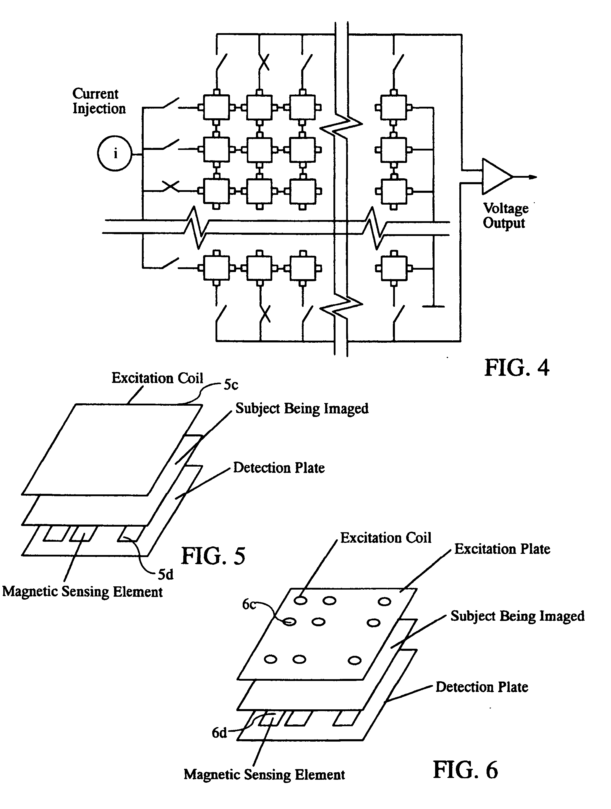
[0146] While present metal detectors can only detect the presence of metal, the invented magnetic scanner may provide the information on size and / or shape of metal object(s). This sensor may consist of say 9 (or any other number of) coils 20c, as illustrated in FIG. 20, to produce an AC magnetic field and say 28 (or any other number of) Hall-effect sensors 20d as detectors. The coils 20c may be energized in turn. When one coil 20c is energized, say 28 (or any other number of) measurements may be taken from the said 28 (or any other number of) Hall-effect sensors 20d. In total say 252 measurements may be taken from the sensor. 3D sensitivity maps may be needed for image reconstruction from the said 252 measurements.

[0147] The sensor panel may consist of say 9 (or any other number of) coils to produce say 10 kHz magnetic fields and the said 28 Hall-effect sensors as detectors as shown in FIG. 2. The sensors, which may be made of s...


PUM


Abstract

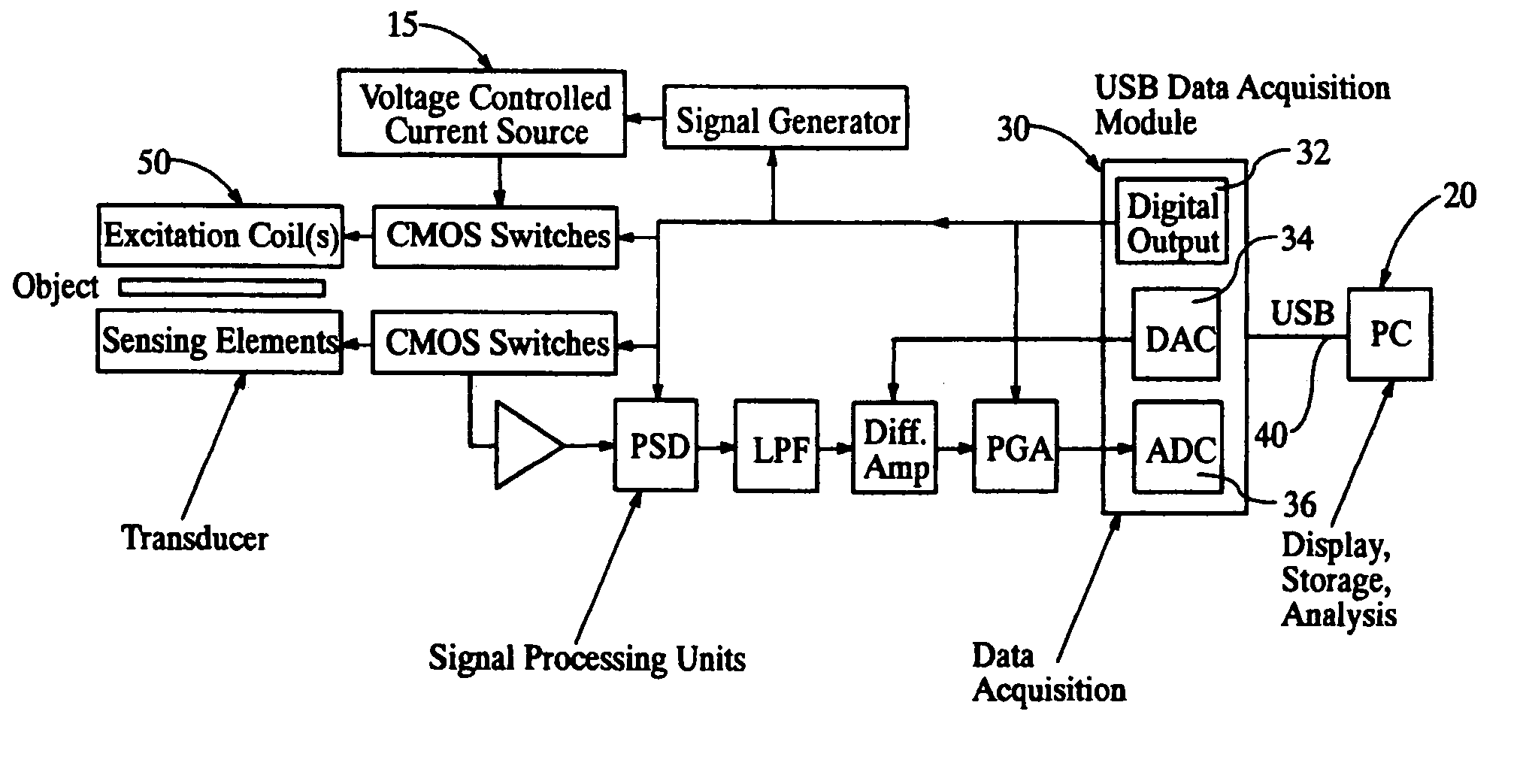
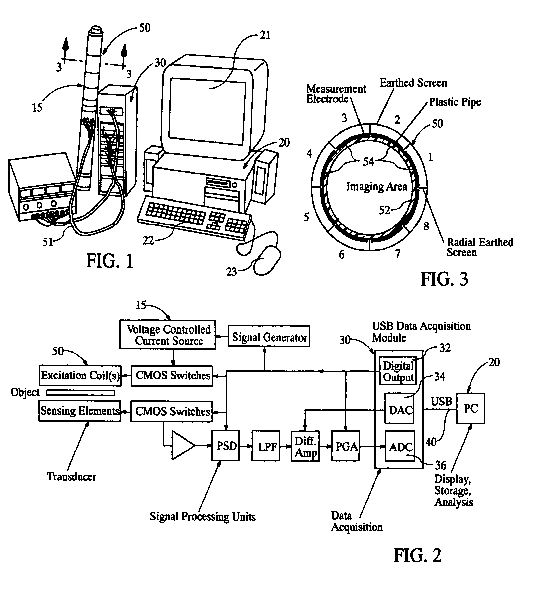
Security scanning devices based on electrical tomography, including tomography systems based on the measurement of capacitance (ECT) and electromagnetic tomography (EMT), in combination with knowledge-based image analysis and understanding. Each device comprises a sensing head or transducer, sensing electronics, image reconstruction and image analysis microprocessor (either microcontroller, DSP, laptop or desktop PC), a display unit and accompanying software for identifying dangerous materials and items. The security scanning devices enable enhancement of image resolution with ECT and EMT. More sensors, more sensitive circuits and flexible / optimal measurement protocols may be employed for obtaining more independent measurements and enable implementation of data fusion to combine the complementary sensitivity of ECT and EMT to different material properties, while providing architecture to implement image knowledge bases, which may characterize objects, whose image attributes are acquired from multiple sensors.

Description

CROSS REFERENCE TO RELATED APPLICATION [0001] This application claims priority of U.S. patent application Ser. No. 11 / 032,424, dated Jan. 10, 2005, which is a continuation of PCT Application No. PCT / IB04 / 004414, dated Jun. 10, 2004, which claims the benefit of U.S. Provisional Patent Application No. 60 / 477,993, filed Jun. 10, 2003.STATEMENT REGARDING FEDERALLY SPONSORED RESEARCH OR DEVELOPMENT [0002] Not Applicable REFERENCE TO MICROFICHE APPENDIX [0003] Not applicable TECHNICAL FIELD [0004] The present invention relates in general to improvements in apparatus and methods for providing real-time 3D images of the contents of containers, such as envelopes, packages and luggage. BACKGROUND OF THE INVENTION [0005] The battle against crime and terrorism has necessarily been a high priority for all civilizations. Since Sep. 11, 2001, homeland security has been receiving the highest attention in airports, post offices and other sectors dealing with public access. In the USA, the Department...

Claims


Application Information

Patent Timeline
Patent Type & Authority Applications(United States)
IPC IPC(8): G01R27/26
CPCA61B5/0522G01N27/221G01V3/08G01R27/00
Inventor YANG, WUQIANGHENNESSEY, A. KATHLEEN
Owner KONSULTEURO LIMITED LIMITED UK
Learn More