Apparatus and method for image configuring

a technology of image configuring and apparatus, applied in the field of apparatus and method for image configuring, can solve the problems of not being able to achieve high-resolution without improving the resolution of the reconstructed object image, being practically difficult to obtain an accurate distance between the object and the micro lens array or between the micro lens array and the photo detector, and being unable to accurately describe the above-mentioned point spread function

Active Publication Date: 2007-07-12
JAPAN SCI & TECH CORP
View PDF0 Cites 198 Cited by
  • Summary
  • Abstract
  • Description
  • Claims
  • Application Information

AI Technical Summary

Benefits of technology

[0029] Thus, relative to the initial image data, the misalignment in hardware is compensated, and the object image configuring that fuses together the compensation of the misalignment and the digital super-resolution processing (processing of the iterative back projection method) can be executed smoothly.

Problems solved by technology

Therefore, since the above mentioned sampling method is a method for merely superposing a plurality of reduced object images of low-resolution formed on a photo detector, the disparities between reduced object images become the position fluctuation of the object information, and there remains a problem of failing to achieve high-resolution without improvement of the resolution of the reconstructed object image.
However, it is practically difficult to obtain an accurate distance between the object and the micro lens array or between the micro lens array and the photo detector, as well as to accurately obtain the influence from the misalignment of the micro lens array and the photo detector.
Therefore, it is impossible to accurately describe the above mentioned point spread function.
Furthermore, in the calculation for inverse matrix, since it is impossible to obtain an accurate inverse matrix of the point spread function, there is no other than a pseudo inverse as an approximate inverse matrix to be utilized.
Consequently, there remains a problem that it is impossible to avoid lowering of the resolution of the object image obtained by reconfiguration using pseudo inverse method.
Also, according to the pixel rearranging method disclosed in the patent literature 1, there remains a problem that, even though it can obtain an image of higher resolution compared with the sampling method and the pseudo inverse method, it cannot avoid deterioration of image quality caused by the limitation of spatial resolution of a compound-eye camera itself compared to the image imaged by a single-eye camera.

Method used


Image

  • Apparatus and method for image configuring
  • Apparatus and method for image configuring
  • Apparatus and method for image configuring

Examples


Embodiment Construction

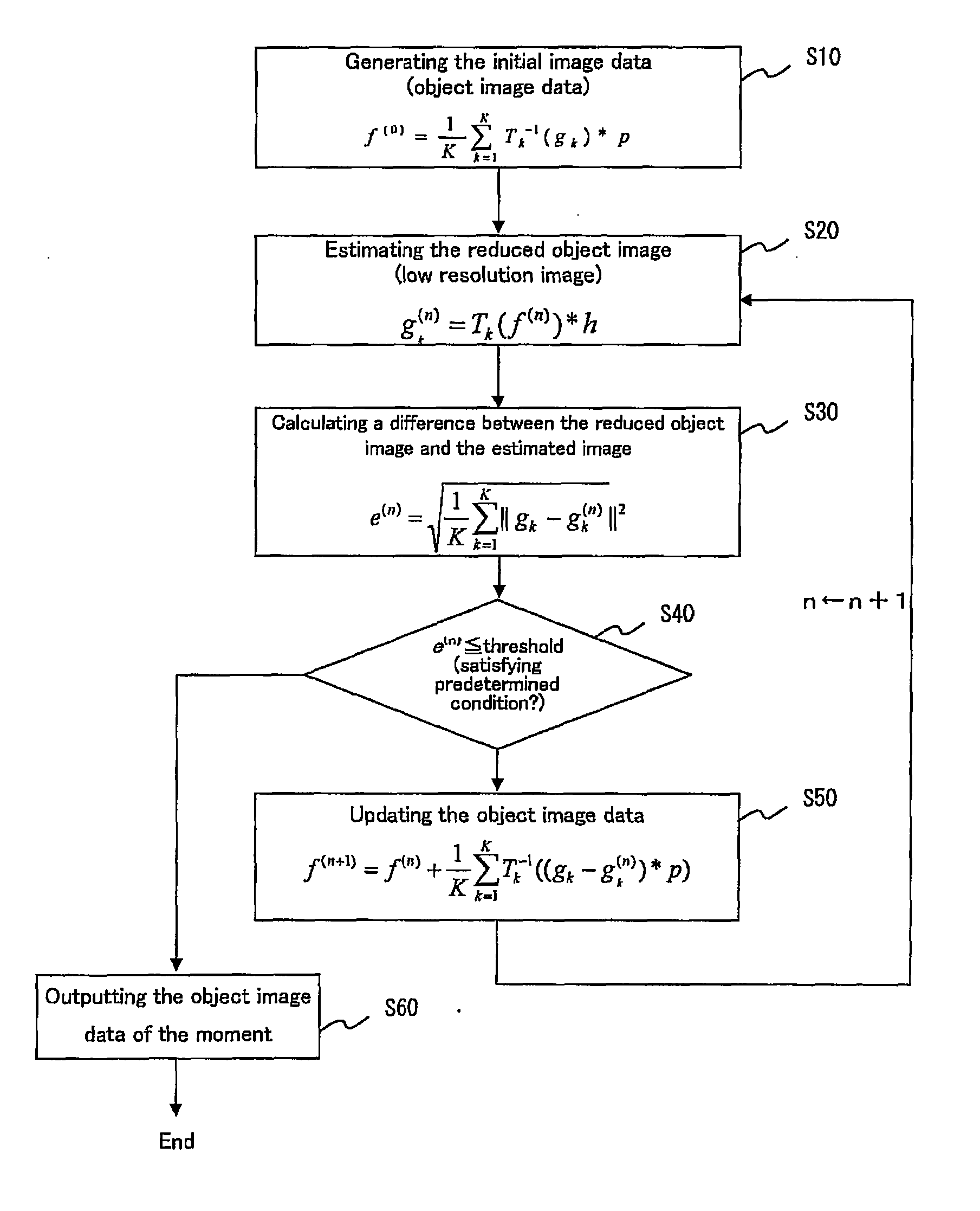
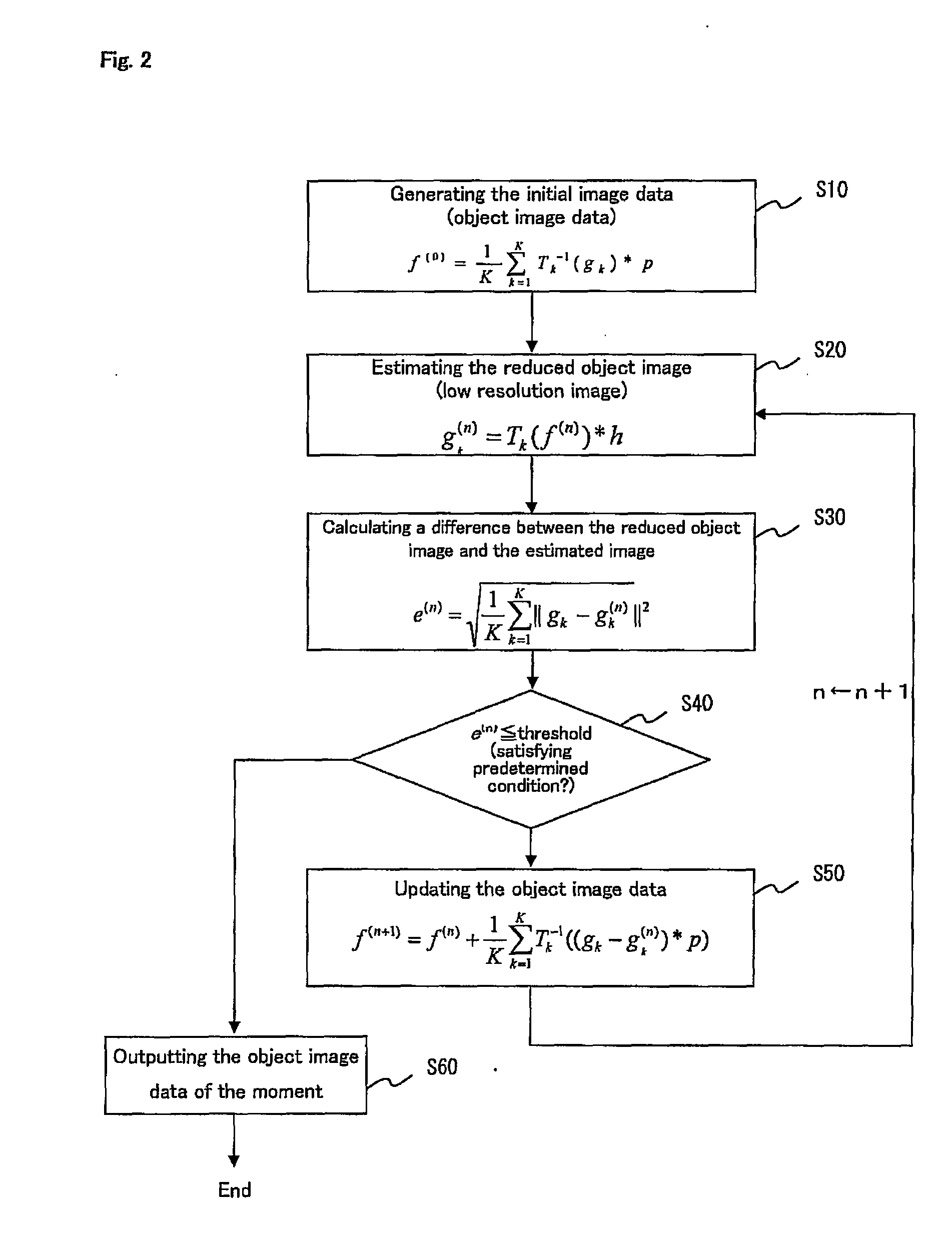
[0040] According to the present Invention, an object image of higher-resolution than the one of a high-resolution image obtained by the pixel rearranging method can be obtained, by generating an initial image data of a single object image based on a image data of a plurality of reduced object images obtained by a compound-eye camera, and then, as setting said initial image data as an initial value, repeatedly conducting the estimating processing of an estimated image of each of the reduced object images from an image data of a single object based on a geometric projection process, as well as the updating processing of the image data of the single object image by projecting the difference between the estimated image of each of the reduced object images and each of the reduced object images in an inverse process of the geometric projection process, until the difference satisfying with the predetermined condition.

[0041] Additionally, this invention achieves to obtain an object image o...


PUM


Abstract

Using image data on a plurality of reduced object images to calculate a shift amount in regard to the gap of relative positions between the reduced object images by a correlation calculation between the reduced object images. A conversion equation is obtained from the shift amount for geometric projection process from the object image to each of the reduced object images. Initial image data on a single object image is generated using image data on the plurality of reduced object images. This and the aforementioned conversion equation, are used to estimate images of each of the reduced object images. A difference between the estimated image of each of the reduced object images and each of the reduced object images is projected in the reverse process of the aforementioned geometric projection process, to update the image data on the single object image. The processes are repeated until the difference satisfies a predetermined condition and a high resolution object image is outputted.

Description

BACKGROUND OF THE INVENTION [0001] 1. Field of the Invention [0002] The present invention relates to the apparatus and method for image configuring capable of configuring a single object image of high resolution from a plurality of reduced object images of low resolution obtained by a compound-eye camera using a plurality of micro lenses. [0003] 2. Description of the Related Art [0004] As an image input apparatus that effectively obtains various image information of high quality, image input apparatuses having structure of obtaining an object image by single optical system that is opposing to the object as a photogenic subject, such as digital cameras and video cameras, have been widely used. However, in these days, for the purpose of downsizing and tinning the image input apparatus, compound-eye cameras mimicking the compound-eye structure of such as insects have been developed. [0005] A compound-eye camera includes a micro-lens array in which a plurality of micro lenses are arrang...

Claims


Application Information

Patent Timeline
Patent Type & Authority Applications(United States)
IPC IPC(8): G06K9/36G06T3/00G06T3/40G06T1/00H04N5/225H04N5/232
CPCG06T3/40H04N5/335H04N5/2254H04N23/55H04N25/00
Inventor TANIDA, JUNNITTA, KOUICHI
Owner JAPAN SCI & TECH CORP
Why Eureka
Try Eureka