
Multi-fiber fiber optic receptacle and plug assembly

a fiber optic receptacle and multi-fiber technology, applied in the field of multi-fiber fiber optic receptacle and plug assembly, can solve the problems of damage to the opposing ferrules and/or optical fibers of the multi-fiber connector, and achieve the effect of improving sealing and increasing mechanical strength

Active Publication Date: 2007-07-12
CORNING OPTICAL COMM LLC
View PDF41 Cites 128 Cited by
  • Summary
  • Abstract
  • Description
  • Claims
  • Application Information

AI Technical Summary

Benefits of technology

[0010] One aspect of the invention is a fiber optic receptacle and plug assembly of like optical connector configuration. The corresponding receptacle and plug each include the same type of single fiber connector or multi-fiber connector, such as but not limited to, a multiple termination (MT) connector. The corresponding receptacle and plug also include one or more electrical connectors associated with electrical conductors in the cable assembly. The receptacle and plug are designed to achieve mass interconnections in both indoor and outdoor installation environments within a compact, yet sufficiently robust assembly. With respect to outdoor environments, the rugged housings of both the receptacle and plug provide improved sealing and increased mechanical strength against pulling forces as compared to conventional optical connections. In one embodiment, the receptacle portion of the assembly may be disposed within a connector port, also referred to herein as a “port,” of a wall of a connection terminal. One or more receptacles may be installed within the connection terminal and remain unoccupied until needed. Once needed, a plug of like optical connector configuration is mated with the corresponding receptacle in a proper orientation as a result of alignment and keying features defined by the receptacle and plug.
[0011] In another aspect, the invention includes robust, corresponding receptacle and plug sub-assemblies comprising a multi-fiber ferrule. Each multi-fiber ferrule is biased within the receptacle and plug by way of a round spring. A ferrule boot combines sealing, ribbon guidance and force centering functions. The sealing function prevents epoxy from leaking between the ferrule and the ferrule boot, thus preventing contamination of a pin clip operable for retaining a pair of guide pins within the ferrule. The back end of the ferrule boot provides a tapered reception window for insertion of multiple individual optical fibers or an optical fiber ribbon. The ferrule boot further defines a convex dome-shaped surface that has its center point axially aligned with a center point on the end face of the ferrule between the two center fibers. A spring centering cuff is disposed on the ferrule boot to align the spring and couple the spring force to the ferrule boot. The cuff seats on the bearing surface of the ferrule boot to provide an axial spring force normal to a tangent of the dome-shaped surface aligned with the center point on the end face of the ferrule. The round spring, spring centering cuff and ferrule boot combine to provide a force centering function that properly aligns the optical fibers of the mating ferrules.
[0012] In another aspect, the invention includes a fiber optic plug including an alignment sleeve, wherein a plug housing and the alignment sleeve define alignment and keying features that allow the plug to be properly mated with a corresponding receptacle defining alignment and keying features that complement those of the fiber optic plug. Thus, a fiber optic plug of a predefined connector configuration may only be received within a receptacle of the same connector configuration. Exclusion features of the alignment sleeve prevent differing fiber optic plugs and receptacles from being mated and thus damaging the opposing ferrules and / or optical fibers of the multi-fiber connectors. The alignment sleeve assists in gross alignment of the ferrules, while guide pins assist in the fine alignment of the optical fibers. The receptacle further defines a shoulder portion having a predetermined shape that is received against the inner surface of a wall of a connection terminal defining an opening for receiving the ferrule, thereby securing the receptacle within the opening through the wall of the connection terminal and preventing the receptacle housing from rotating within the connector port.

Problems solved by technology

Exclusion features of the alignment sleeve prevent differing fiber optic plugs and receptacles from being mated and thus damaging the opposing ferrules and / or optical fibers of the multi-fiber connectors.

Method used


Image

  • Multi-fiber fiber optic receptacle and plug assembly
  • Multi-fiber fiber optic receptacle and plug assembly
  • Multi-fiber fiber optic receptacle and plug assembly

Examples


Embodiment Construction

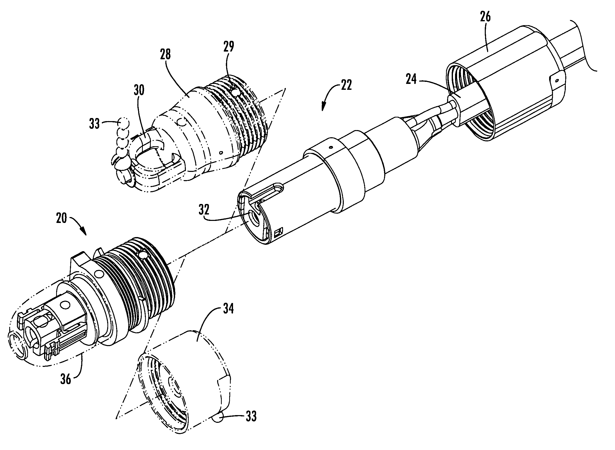
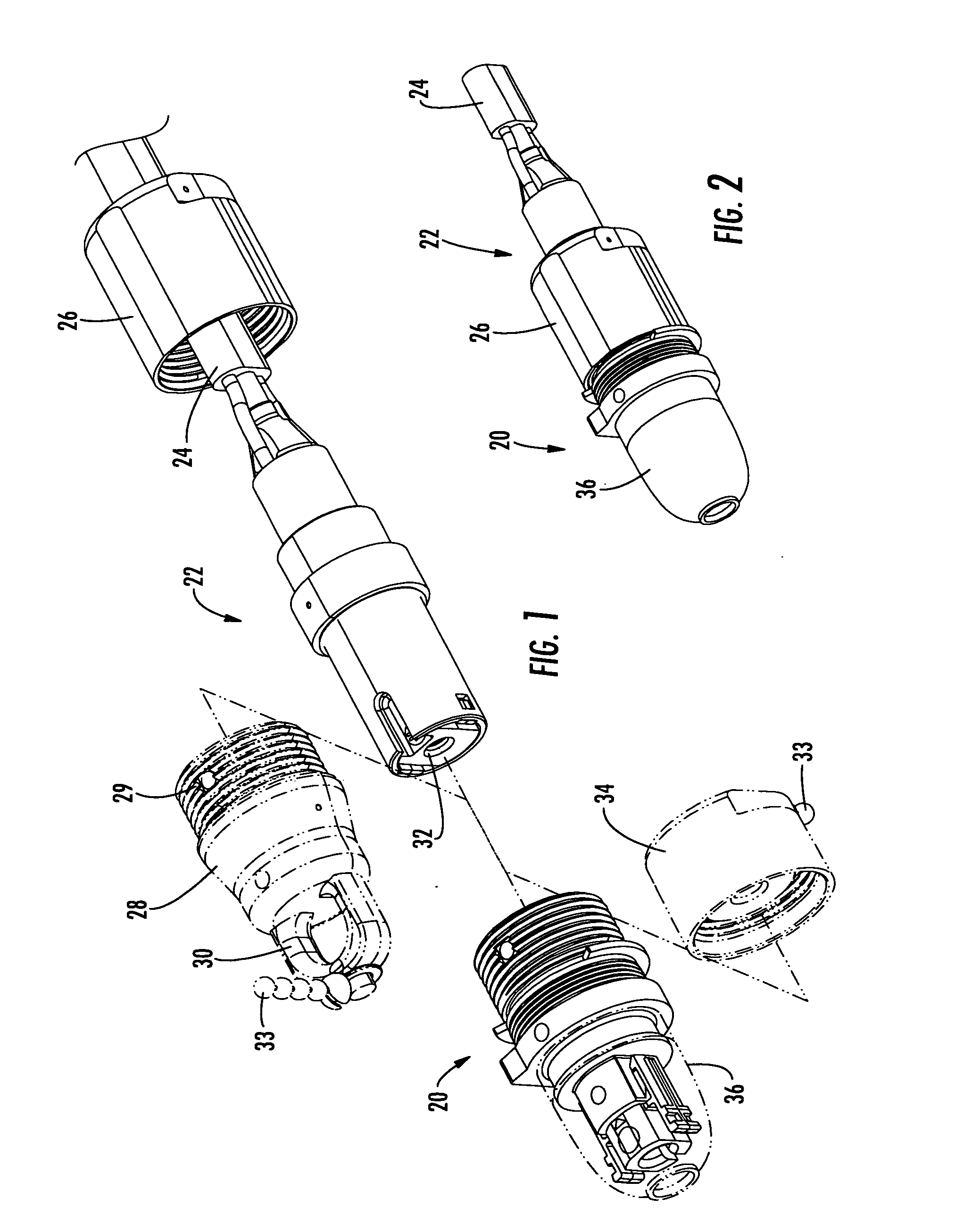
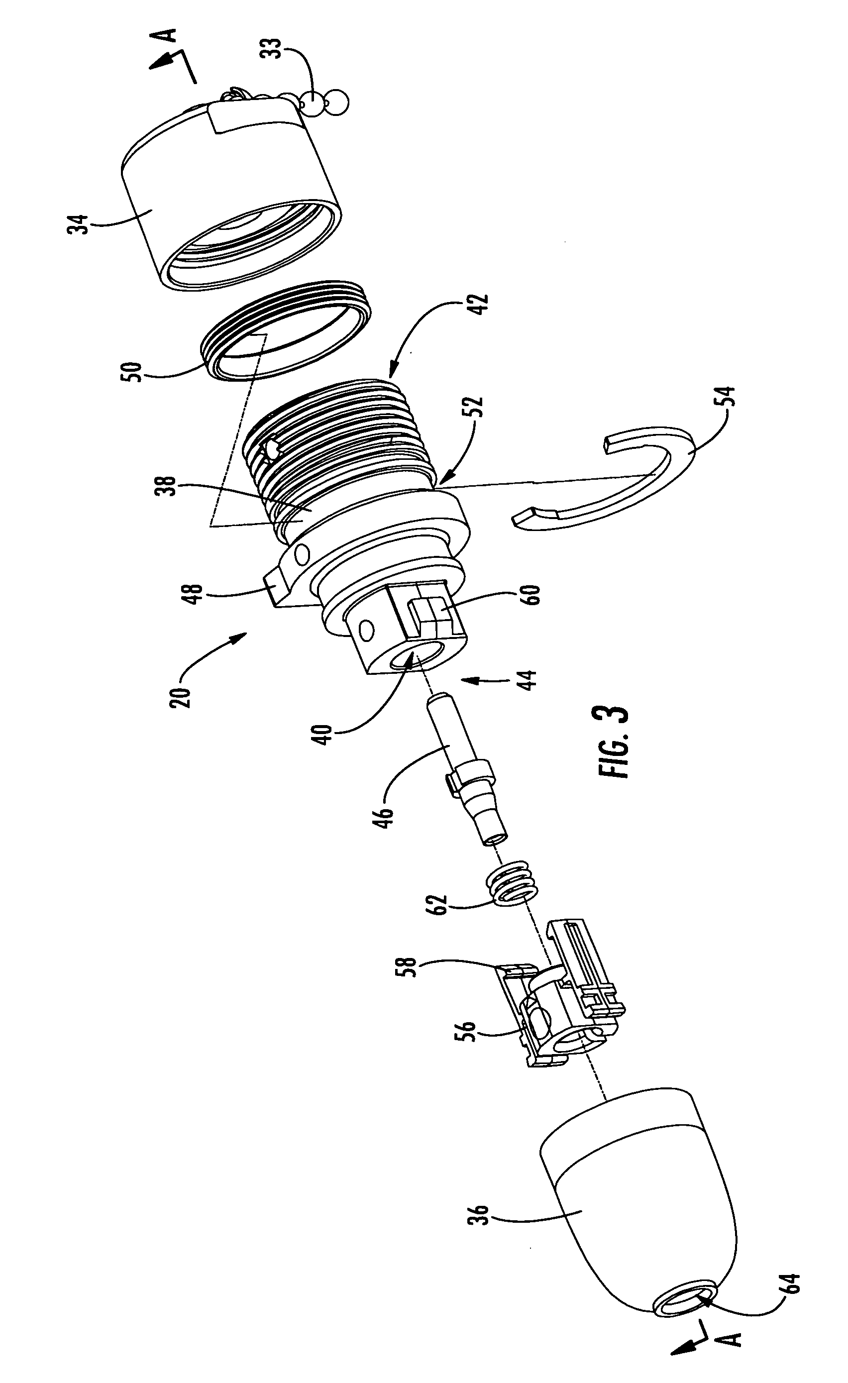
[0049] Reference will now be made in detail to the present preferred embodiments of the invention, and examples of which are illustrated in the accompanying drawings. Whenever possible, the same reference numerals will be used throughout the drawings to refer to the same or like parts. One embodiment of the multi-fiber fiber optic receptacle and plug assembly of the invention is shown in FIG. 1 with the fiber optic receptacle and corresponding fiber optic plug designated generally throughout by reference numerals 20 and 22, respectively.

[0050] Referring now to FIGS. 1-10, the exemplary embodiment of the fiber optic receptacle 20 and corresponding fiber optic plug 22 are shown. Although not shown, the receptacle 20 is typically mounted within a connector port defined by a wall of an enclosure, such as a connection terminal in a fiber optic communications network. In a particularly advantageous embodiment, the receptacle 20 is mounted within an opening formed through an external wall...


PUM


Abstract

There is provided a fiber optic receptacle and plug assembly adapted to provide electrical connectors for electrical conductors. The receptacle and plug define complimentary alignment and keying features for ensuring that the plug is mated with the receptacle in a predetermined orientation. An alignment sleeve is disposed within the plug for receiving a multi-fiber receptacle ferrule and a multi-fiber plug ferrule. The fiber optic receptacle and corresponding plug each include a biasing member assembly for urging the receptacle ferrule and the plug ferrule towards one another, wherein the biasing member assembly includes a spring, a spring centering cuff and a ferrule boot that operatively engage the rear of the receptacle ferrule and the plug ferrule, respectively, to substantially center a spring biasing force on the end face of the receptacle ferrule and the plug ferrule. The electrical connectors of the receptacle and plug are preferably provided separate from the biasing member assembly.

Description

CROSS REFERENCE TO RELATED APPLICATION [0001] This application is a continuation-in-part of copending U.S. patent application Ser. No. 11 / 076,684, filed on Mar. 10, 2005, which is hereby incorporated herein in its entirety by reference.BACKGROUND OF THE INVENTION [0002] 1. Field of the Invention [0003] The present invention relates generally to a fiber optic receptacle and plug assembly, and more particularly, to a multi-fiber fiber optic receptacle and plug assembly utilizing multiple termination (MT) style ferrules for interconnecting a plurality of optical fibers within a communications network. [0004] 2. Technical Background [0005] Optical fiber is increasingly being used for a variety of broadband applications including voice, video and data transmissions. As a result, fiber optic communications networks include a number of interconnection points at which multiple optical fibers are interconnected. Fiber optic networks also include a number of connection terminals, examples of ...

Claims


Application Information

Patent Timeline
Patent Type & Authority Applications(United States)
IPC IPC(8): G02B6/36
CPCG02B6/3817G02B6/3821G02B6/3825G02B6/4465G02B6/3878G02B6/3885G02B6/3894G02B6/3849G02B6/3889G02B6/38875G02B6/545
Inventor LEWALLEN, CHRISTOPHER PAULLUTHER, JAMES P.THEUERKORN, THOMAS
Owner CORNING OPTICAL COMM LLC
Features
  • Generate Ideas
  • Intellectual Property
  • Life Sciences
  • Materials
  • Tech Scout
  • Unparalleled Data Quality
  • Higher Quality Content
  • 60% Fewer Hallucinations
Learn More