Anti-wear device for a guide pivot of a variable-pitch vane of a turbomachine compressor

Inactive Publication Date: 2007-07-12
SN DETUDE & DE CONSTR DE MOTEURS DAVIATION S N E C M A
View PDF8 Cites 17 Cited by
  • Summary
  • Abstract
  • Description
  • Claims
  • Application Information

AI Technical Summary

Benefits of technology

[0006]A main object of the present invention is thus to mitigate such drawbacks by proposing a vane and

Problems solved by technology

In modern turbomachines, variable-pitch vanes are subjected to high levels of mechanical stress that lead to premature wear of their guide

Method used


Image

  • Anti-wear device for a guide pivot of a variable-pitch vane of a turbomachine compressor
  • Anti-wear device for a guide pivot of a variable-pitch vane of a turbomachine compressor

Examples


Embodiment Construction

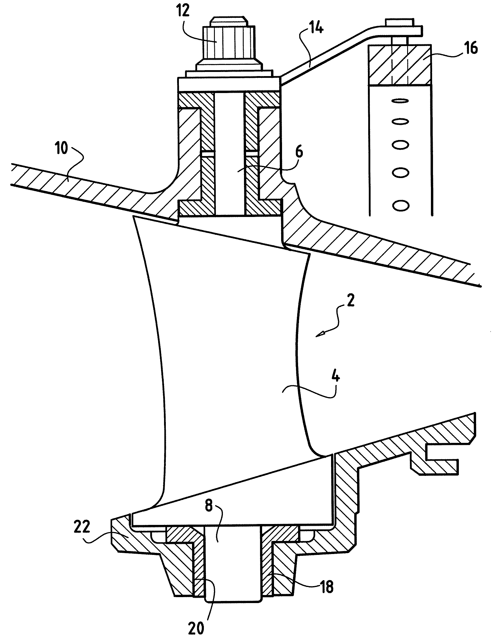
[0018]With reference to FIG. 1, the variable-pitch vanes 2 of the high pressure compressor of the turbomachine are distributed in circular stages disposed between stages of moving blades (not shown) that are secured to a rotor (not shown) of the turbomachine.

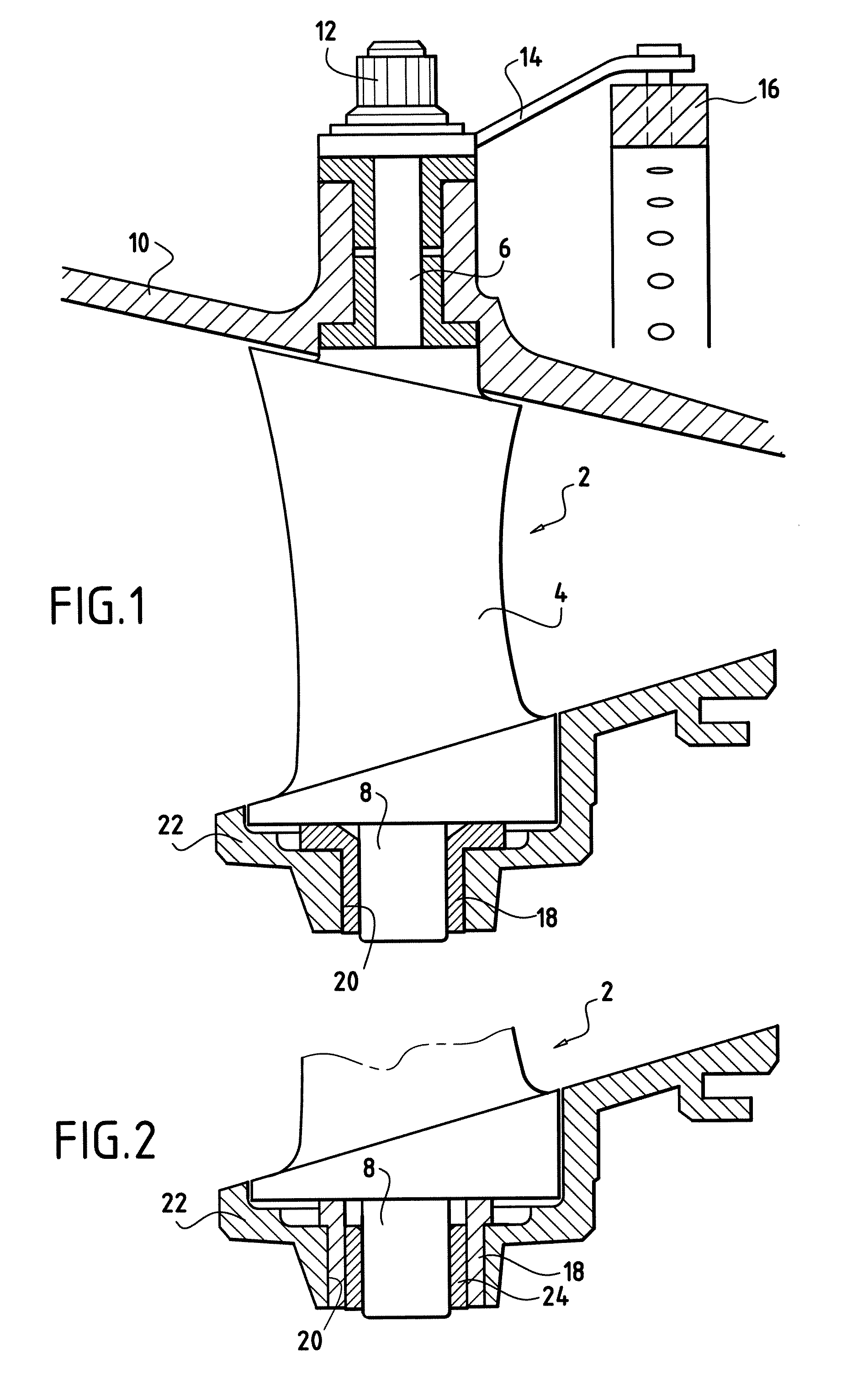
[0019]Each variable-pitch vane 2 of a circular stage is in the form of an airfoil 4 terminating at a radially outer end (or vane head) in a control pivot 6 (or top pivot), and at a radially inner end (or blade root) by a guide pivot 8 (or bottom pivot).

[0020]The control pivot 6 passes through a stator casing 10 of the turbomachine and co-operates with a member for controlling vane pitch. For this purpose, the control pivot 6 is terminated by a head 12 having engaged thereon one end of a control link 14 whose other end co-operates with a control ring 16.

[0021]The links 14 and the control ring 16 form the member for controlling the pitch of the vanes. Turning the control ring 16 about the axis of the turbomachine serves to turn th...


PUM


Abstract

The invention relates to a variable-pitch vane for a turbomachine compressor, the vane including a bushing mounted to rotate about a guide pivot of the vane for mounting in a casing of the turbomachine, the pivoting contact between the bushing and the guide pivot being of the nickel-graphite and titanium type.

Description

BACKGROUND OF THE INVENTION[0001]The present invention relates to the general field of variable-pitch vanes. A particular application lies in the field of aviation, in particular for controlling the angular pitch of the air inlet guide vanes in turbomachine compressors.[0002]In a turbomachine, the high pressure compressor is typically made up of a plurality of variable-pitch vane stages that serve to modify the flow characteristics of the gas depending on the operating speed of the turbomachine.[0003]The variable-pitch vanes in a given stage have respective head control pivots and root guide pivots, the control pivot passing through a stator casing of the turbomachine and co-operating with a member for controlling the pitch angle of the vanes, and the guide pivot being mounted to pivot in a bushing housed in a recess in an inside ring of the turbomachine casing. By acting on the control member, it is possible to vary the pitch angle of the vanes in the stage in question.[0004]The va...

Claims


Application Information

Patent Timeline
IPC IPC(8): F04D29/56
CPCC23C4/04F01D5/3092F05D2300/133F05D2300/509F01D17/162F04D29/563F16C2360/23
Inventor LESNEVSKY, LEONIDTROSHIN, ALEXANDERVIGNEAU, JOEL OLIVIER ALFRED ABEL
Owner SN DETUDE & DE CONSTR DE MOTEURS DAVIATION S N E C M A
Why Eureka
Try Eureka