Constant velocity joint

Inactive Publication Date: 2007-07-12
HONDA MOTOR CO LTD
View PDF7 Cites 21 Cited by
  • Summary
  • Abstract
  • Description
  • Claims
  • Application Information

AI Technical Summary

Benefits of technology

[0034] According to the constant-velocity joint of the present invention, each of first guide grooves held in contact with a corresponding one of balls at a single point has a transverse cross section extending perpendicularly to the axial direction and having a single arc shape, and each of second guide grooves held in contact with a

Problems solved by technology

According to the first and second methods, however, the retainer 4 becomes heavy and has a greater width, and the balls 3 tend to bite into the guide grooves 1b, reducing the durability of the outer member 1.
However, the fixed constant-velocity universal joint disclosed in Japanese Laid-Open Patent Publication No. 2001-330051 is made of up a large number of parts, is highly costly to manufacture, and is difficult to produce in practice.
As the ball grooves in the outer race and the ball grooves in the inner race are offset equal distances from the joint center, the depths of the ball grooves in the outer and inner races are not uniform in the axial direction.
With the structure disclosed in the general document, since the depths of the ball grooves in the outer race and the ball grooves in the inner race are small, when the constant-velocity joint operates at large joint angles or under high loads, the contact ellipse of the balls protrudes from the ball grooves, tending to bring the balls onto shoulders (edges) of the ball grooves, causing the balls to crack or to wear down the shoulders (edges) of the ball grooves, resulting in a reduction in the durability of the constant-velocity joint.
Furthermor

Method used


Image

  • Constant velocity joint
  • Constant velocity joint
  • Constant velocity joint

Examples


Embodiment Construction

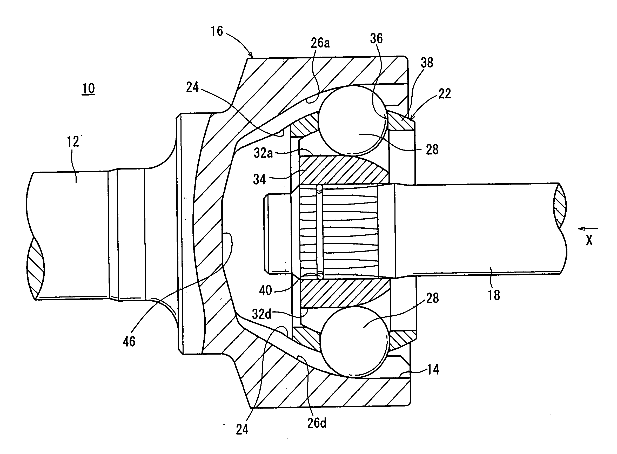
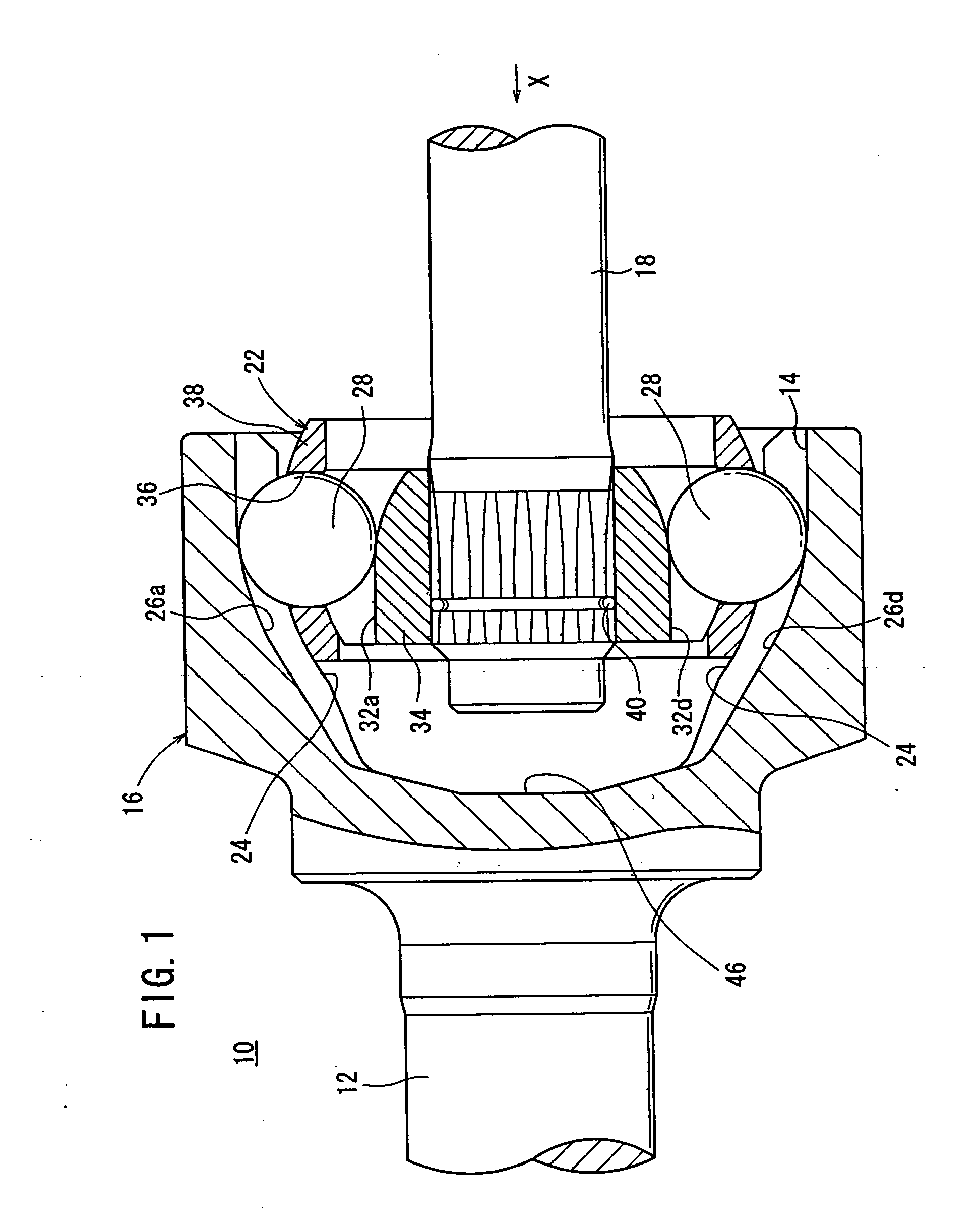
[0078]FIG. 1 shows a constant-velocity joint 10 according to an embodiment of the present invention. In the description which follows, a longitudinal cross section refers to a cross section along the axial direction of a first shaft 12 and a second shaft 18, and a transverse cross section to a cross section perpendicular to the axial direction.

[0079] The constant-velocity joint 10 is basically constructed of a bottomed cylindrical outer cup (outer member) 16 integrally joined to an end of a first shaft 12 and having an opening 14 that opens away from the first shaft 12, and an inner member 22 fixed to an end of a second shaft 18 and housed in the outer cup 16.

[0080] As shown in FIGS. 1 and 3, the outer cup 16 has a spherical inside-diameter surface 24 on its inner wall. The inside-diameter surface 24 has six first guide grooves 26a through 26f extending in the axial direction and angularly spaced at 60-degree intervals around the axis thereof.

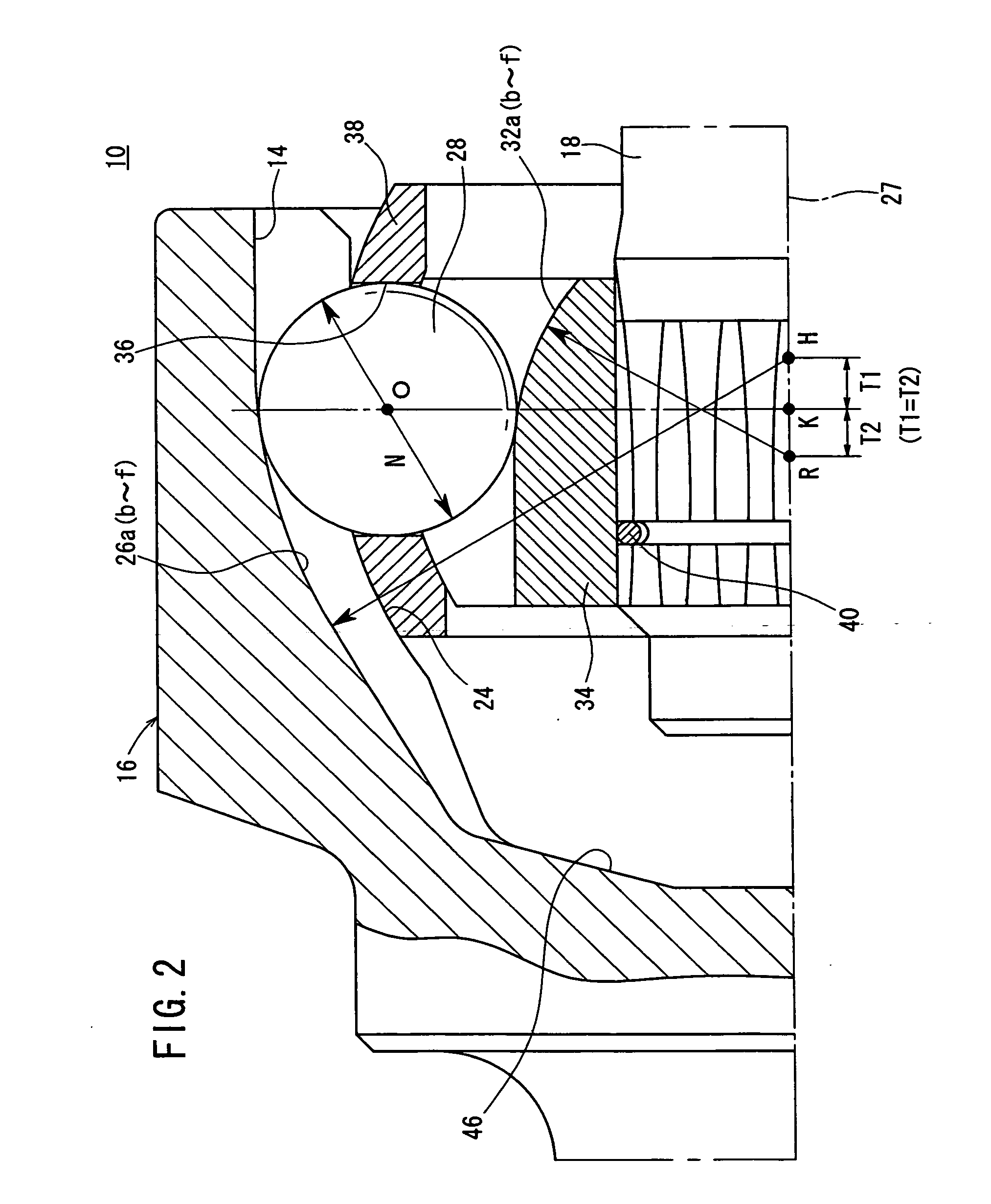
[0081] As shown in FIG. 2, the first ...


PUM


Abstract

Lateral cross-sections of first guiding grooves provided in the inner wall surface of an outer cup are formed in a circular arc shape for one point contact with balls, and lateral cross-sections of second guiding grooves provided in the outer wall surface of an inner ring are formed in an elliptic arc shape for two-point contact with the balls. The diameter of a ball and an offset amount between a first and a second groove is set to satisfy the expression of 0.12≦V≦0.14 with V being the ratio of the two values.

Description

TECHNICAL FIELD [0001] The present invention relates to a constant-velocity joint for connecting a transmission shaft to another transmission shaft in an automotive driveline, for example. BACKGROUND ART [0002] Heretofore, automotive drivelines employ a constant-velocity joint for connecting a transmission shaft to another transmission shaft and transmitting rotational power to the axles. In recent years, there has been a growing need for lighter constant-velocity joints and hence smaller constant-velocity joints. The mechanical strength, durability, load capacity, etc. of constant-velocity joints are determined by the basic dimensions of various components of the constant-velocity joints. It is necessary to determine those basic dimensions for smaller constant-velocity joints while maintaining the mechanical strength, durability, load capacity, etc. at desired levels. [0003] Japanese Laid-Open Patent Publication No. 2001-330051 discloses a fixed constant-velocity universal joint ha...

Claims


Application Information

Patent Timeline
IPC IPC(8): F16D3/00F16D3/223F16D3/2237F16D3/224
CPCF16D3/223F16D3/2237F16D2003/22309F16D2003/22303F16D3/224Y10S464/906
Inventor NAKAO, SHOUICHIIDO, KAZUKIYOKOYAMA, AKIRA
Owner HONDA MOTOR CO LTD
Why Eureka
Try Eureka