Catheter introducer system

Inactive Publication Date: 2007-07-12
ARIZONA MEDICAL SYST
View PDF92 Cites 38 Cited by
  • Summary
  • Abstract
  • Description
  • Claims
  • Application Information

AI Technical Summary

Benefits of technology

[0007] When the catheter is at a desired location, it may be fixed longitudinally in place and blood loss through the sheath minimized by selective tightening of a hemostasis valve that includes a chuck that radially grips th

Problems solved by technology

This may cause trauma to the derma and blood vessel, or require a second needle insertion if the tip is damaged to the extent it prevents suita

Method used


Image

  • Catheter introducer system
  • Catheter introducer system
  • Catheter introducer system

Examples


Embodiment Construction

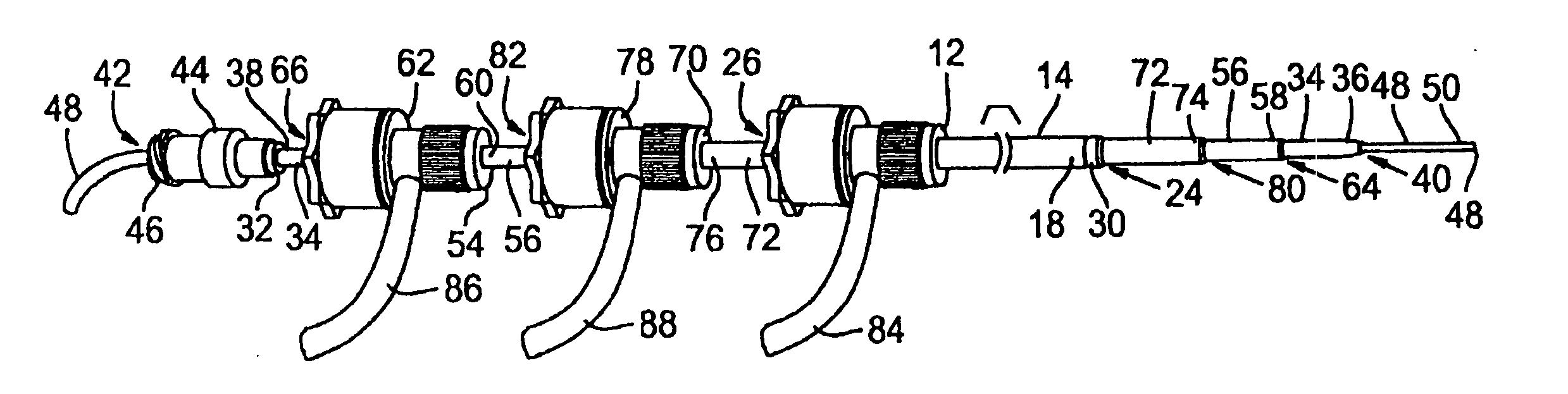
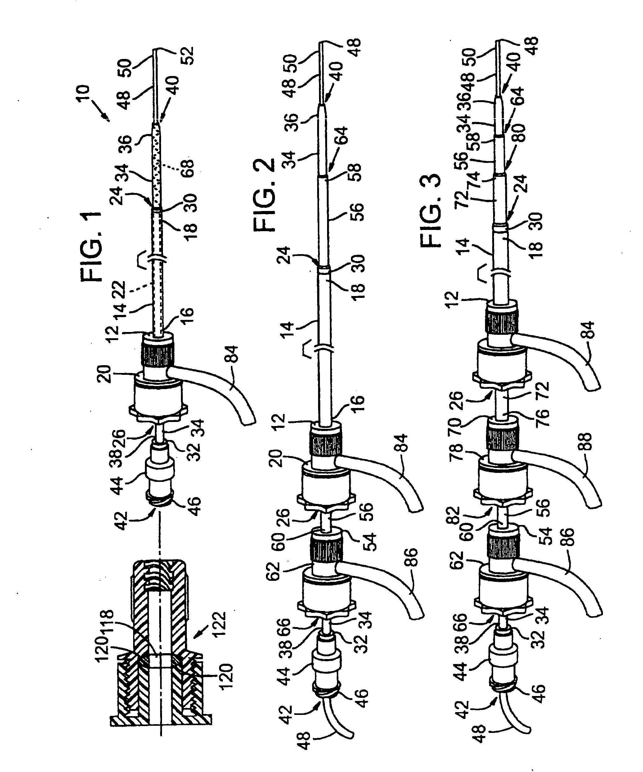
[0022] A catheter introducer system in accordance with the present invention is indicated generally at 10 in FIG. 1. Catheter introducer system 10 includes a sheath 12 having a generally elongate, typically cylindrical body 14 with a proximal end 16 and a distal end 18. Body 14 of sheath 12 is coupled at proximal end 16 to a housing 20. A central, typically cylindrical lumen 22 is defined within sheath 12 extending out through a distal opening 24 and a proximal opening 26. Sheath 12 is thus configured to receive a catheter 28 (FIG. 5) for longitudinal movement through and torsional movement within lumen 22.

[0023] Body 14 of sheath 12, is typically composed substantially of a flexible material, such as a plastic, polymeric material, preferably a hydrophilic material. Body 14 may include a reinforcement, such as stainless steel ring 30, to prevent buckling or crimping of distal end 18 at opening 24 when sheath 12 is inserted into a human blood vessel. The stainless steel ring 30 on t...


PUM


Abstract

A catheter introducer system is provided with a catheter sheath having a valve providing for a friction fit around a catheter. The friction fit is selectively adjustable to vary between a first configuration for longitudinal movement of the catheter through the valve and a second configuration for holding the catheter longitudinally in place. The valve may includes a chuck to grip the catheter radially. The chuck may include an annular base and an opposed annular clamp, and a washer disposed between the base and the clamp. At least one of the base and the clamp may include a beveled surface that forces the washer radially inwardly as the base and the clamp are drawn together. The system also includes one or more dilators layered within the sheath. The layered dilators and sheaths are typically softer and more hydrophilic proceeding from the innermost dilator out to the sheath. The dilator may be reinforced by a wire embedded in the body of the dilator. The distal tip of the sheath may be stiffened by a ring affixed adjacent the distal end. The sheath may include in the innermost dilator a trocar formed of a flexible, hollow outer wire and an inner stiff needle, which can extend beyond the wire for piercing and be withdrawn to relax the wire for advancement of the dilator.

Description

BACKGROUND [0001] Catheters typically are inserted into a blood vessel through a sheath which is fixed in place relative to the blood vessel. The sheath protects the vessel and adjacent derma around the point of insertion while the catheter is advanced and withdrawn as necessary for the particular treatment being applied. The sheath is prepared for insertion by first placing a dilator within the lumen of the sheath and a needle or pointed wire within the lumen of the dilator. The needle or wire is used to pierce the derma and the blood vessel's wall and then is advanced into the blood vessel's lumen. Then the dilator is advanced along the wire without moving the needle or wire so that the tip of the dilator passes through the derma and blood vessel wall, expanding the diameter of the opening into the blood vessel. [0002] At this point, with the dilator tip within the blood vessel lumen, the needle or wire may be withdrawn from the blood vessel. The sheath may then be advanced along ...

Claims


Application Information

Patent Timeline
IPC IPC(8): A61M5/178A61B17/34A61MA61M25/06A61M29/00A61M39/06
CPCA61B17/3415A61B17/3462A61B17/3498A61B2017/3441A61M25/0662A61M2039/0633A61M39/0613A61M2025/0004A61M2025/0681A61M2025/0687A61M29/00
Inventor HEUSER, RICHARD R.
Owner ARIZONA MEDICAL SYST
Why Eureka
Try Eureka