Image display system

Inactive Publication Date: 2007-07-12
SEIKO EPSON CORP
View PDF4 Cites 12 Cited by
  • Summary
  • Abstract
  • Description
  • Claims
  • Application Information

AI Technical Summary

Benefits of technology

[0007]According to an aspect of the invention, there is provided an image display system including a projector including an RFID tag section and a first wireless LAN section whose network setting is automatically performed, and a wireless terminal including an RFID reading device and a second wireless LAN section. In the image display system, the image display system transmits RFID tag information including information for performing network setting to the wireless terminal in response to the RFID tag section receiving an electronic wave emitted by the RFID reading device of the wireless terminal, and the wireless terminal, in response to the RFID reading device receiving the RFID tag information, automatically performs the network setting to the second wireless LAN section based on the RFID tag information, and makes the second wireless LAN section transmit a predetermined content to the first wireless LAN section. In this aspect of the invention, by locating the projector provided with the RFID tag section in a range in which it can receive the radio wave emitted by the RFID reading device, the network settings are performed on the second wireless LAN section of the wireless terminal, thus the communication between the projector and the wireless terminal is automatically established. Therefore, the user can be released from the troublesome manual network settings performed in the past. Further, this becomes particularly effective for the user who has little knowledge about the network technology. As described above, since there is no need for manually performing the network settings of the projector and the wireless terminal, the operation for making the projector display the contents of the wireless terminal side becomes easy.
[0008]Further, according to another aspect of the invention, there is provided an image display system wherein the projector receives the content from the wireless terminal by the first wireless LAN section to display the content. In this aspect of the invention, since there is no need for manually performing the network settings of the wireless terminal, the operation for displaying the content of the wireless terminal becomes easy.
[0009]Further, according to another aspect of the invention, there is provided an image display system wherein the projector and the wireless terminal are connected to each other in the ad-hoc mode. Since in this aspect of the invention they are wireless-connected to each other in the ad-hoc mode without transiting an access point, the transmission rate of the content becomes faster.
[0011]Further, according to another aspect of the invention, there is provided an image display system wherein the RFID tag section further transmits, as the RFID tag information, information of the content and a play type. In this aspect of the invention, since the content is transmitted by transmitting such information, the trouble of performing setting for playing the content after the communication has established can be saved.

Problems solved by technology

However, it is a very troublesome work for the user who does not have enough knowledge about the network to perform network setting to each of the devices for establishing communication.

Method used


Image

  • Image display system
  • Image display system
  • Image display system

Examples


first embodiment

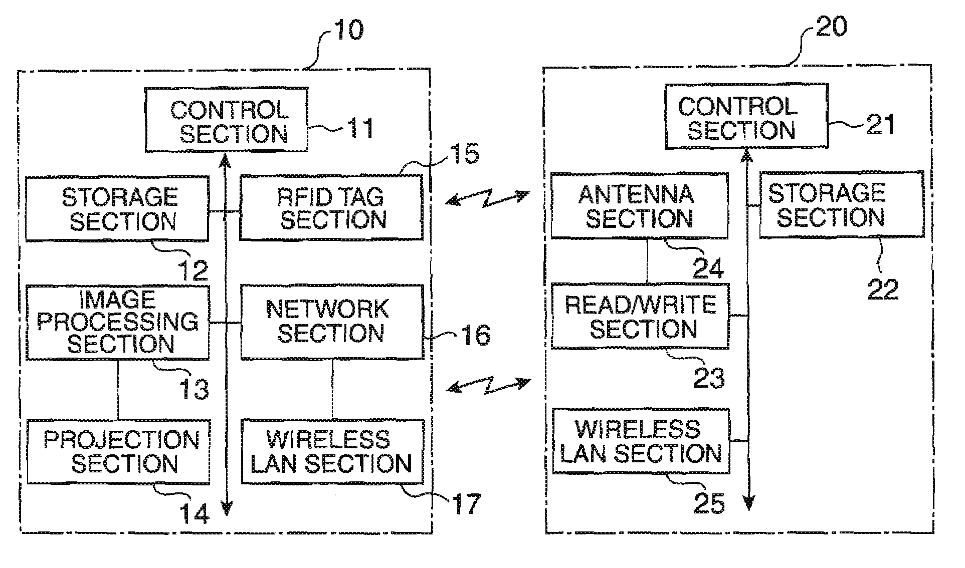
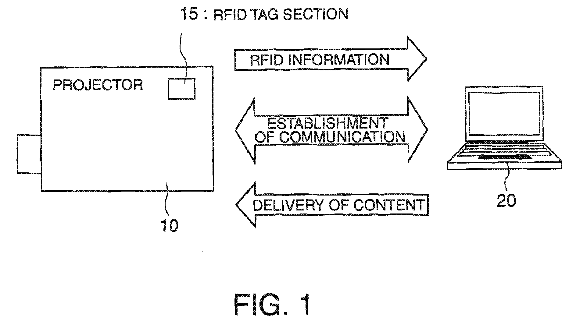
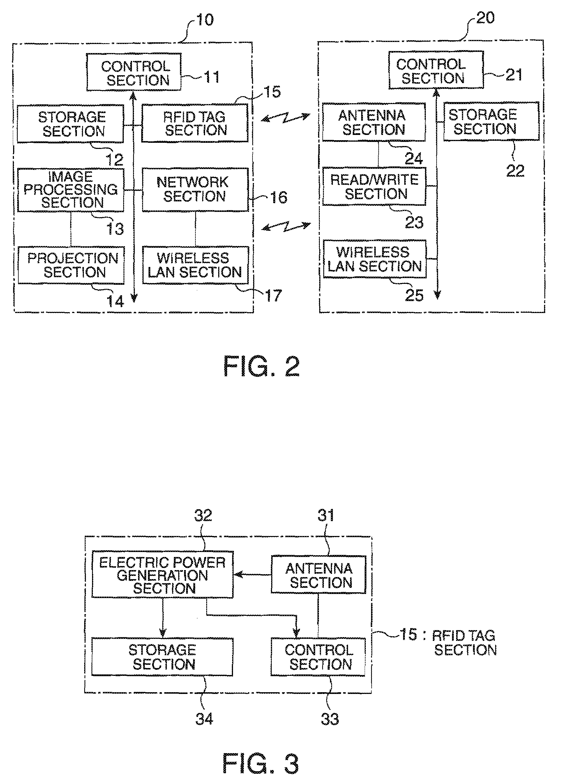
[0019]FIG. 1 is a configuration diagram of an image display system according to a first embodiment of the invention, and FIG. 2 is a block diagram showing details of a projector 10 and a personal computer 20 composing the image display system. It should be noted that FIG. 2 shows only parts extracted from the projector 10 and the personal computer 20, which are necessary for explanations. The projector 10 is mainly composed of a control section 11, storage section 12, an image processing section 13, a projection section 14, a radio frequency identification (RFID) tag section 15, a network section 16, and a wireless LAN section 17. The personal computer 20 is mainly composed of a control section 21, a storage section 22, a read / write section 23, an antenna section 24, and a wireless LAN section 25. The control section 11 of the projector 10 and the control section 21 of the personal computer 20 are each mainly composed of a CPU and a storage device storing a program for making the CP...

second embodiment

[0033]In the first embodiment, an example of establishing the net connection with the wireless LAN between one projector 10 and one personal computer 20 is explained. As a second embodiment, the action in the case in which the personal computer 20 is supposedly connected to a certain projector 10 (the projector is referred to as a projector A) and another projector (referred to as a projector B) is further implemented will be explained.

[0034]FIG. 5 is a flowchart showing the action of the personal computer 20 in the second embodiment, which is illustrated focusing on the differences from FIG. 4. When the control section 21 of the personal computer 20 receives the RFID tag information of the projector B (S21), and then it is judged from the RFID tag information that the projector B is supported by the personal computer 20 (S22), if there is subsequently a condition of already connecting to the projector A, the control section 21 transmits a message to the projector A that it disconne...

third embodiment

[0036]Further, although an example of personal computer 20 as the wireless terminal is explained in the first embodiment, the personal computer 20 can be either of the server or the client, and it can be configured to be connected to a database storing the content and to read the content therefrom. Further, the wireless terminal is not limited to the personal computer 20, but can be other equipment providing that the wireless LAN can be established therewith. Further, although the example of the ad-hoc mode is explained as an example of the wireless connection, the connection in the infrastructure mode can also be adopted.


PUM


Abstract

An image display system includes a projector having an RFID tag section and a first wireless LAN section whose network setting is automatically performed, and a wireless terminal including an RFID reading device and a second wireless LAN section, wherein the image display system transmits RFID tag information including information for performing network setting to the wireless terminal in response to the RFID tag section receiving an electronic wave emitted by the RFID reading device of the wireless terminal, and the wireless terminal, in response to the RFID reading device receiving the RFID tag information, automatically performs the network setting to the second wireless LAN section based on the RFID tag information, and makes the second wireless LAN section transmit a predetermined content to the first wireless LAN section.

Description

BACKGROUND[0001]1. Technical Field[0002]The present invention relates to an image display system provided with a projector, and in particular to a network connection between the projector and a wireless terminal.[0003]2. Related Art[0004]In the past, as an image display system utilizing a projector, there has been proposed a display system for advertisement use such as delivering contents via a network, and displaying them with a projector (see JP-A-2005-167573). In the system, the user is required to perform network setting of each of the devices for establishing a network between the projector and a server.[0005]However, it is a very troublesome work for the user who does not have enough knowledge about the network to perform network setting to each of the devices for establishing communication.SUMMARY[0006]In view of the problems described above, some aspects of the invention have an advantage of providing an image display system capable of automatically performing the network se...

Claims


Application Information

Patent Timeline
IPC IPC(8): G06F7/00G06F17/00G05B19/00G06F15/177
CPCH04L29/12254H04L67/14H04L61/2038H04L61/5038
Inventor ICHIEDA, HIROYUKI
Owner SEIKO EPSON CORP
Why Eureka
Try Eureka