Miter Saw Having Slide Mechanism

a technology of sliding mechanism and miter saw, which is applied in the field of miter saws, can solve the problems of operator discomfort, blowing amount of cutting chips, and sensitive to changes in such blowing amount of cutting chips, and achieve the effect of reducing the amount of cutting chips discharged

Inactive Publication Date: 2007-07-19
KOKI HLDG CO LTD
View PDF0 Cites 21 Cited by
  • Summary
  • Abstract
  • Description
  • Claims
  • Application Information

AI Technical Summary

Benefits of technology

[0008]It is therefore, an object of the present invention to provide a miter saw capable of reducing an amount of cutting chips discharged particularly during terminal phase of cutting operation.

Problems solved by technology

Consequently, an operator become sensitive to changes in such cutting chips blowing amount and feel uncomfortable.

Method used


Image

  • Miter Saw Having Slide Mechanism
  • Miter Saw Having Slide Mechanism
  • Miter Saw Having Slide Mechanism

Examples


Embodiment Construction

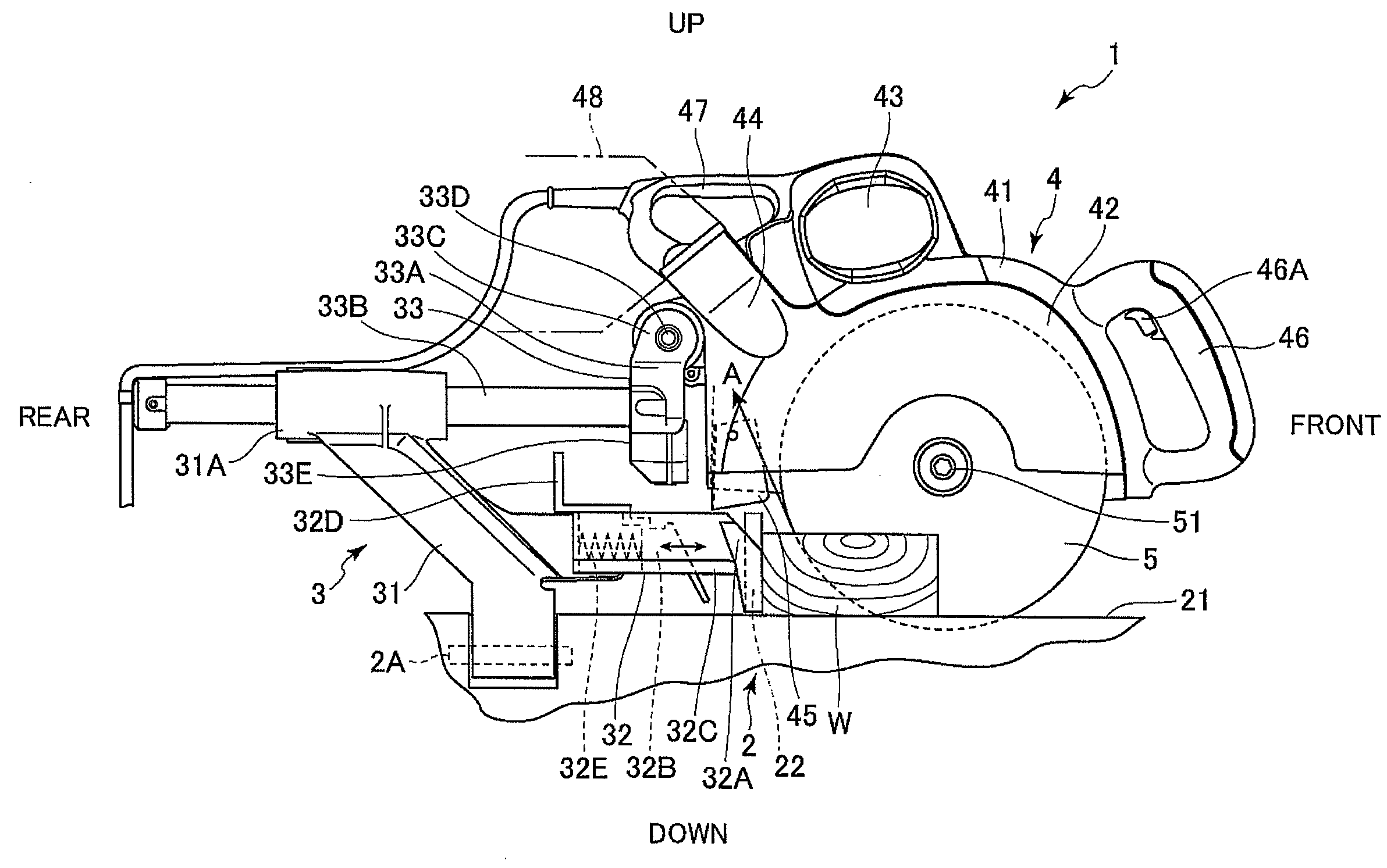
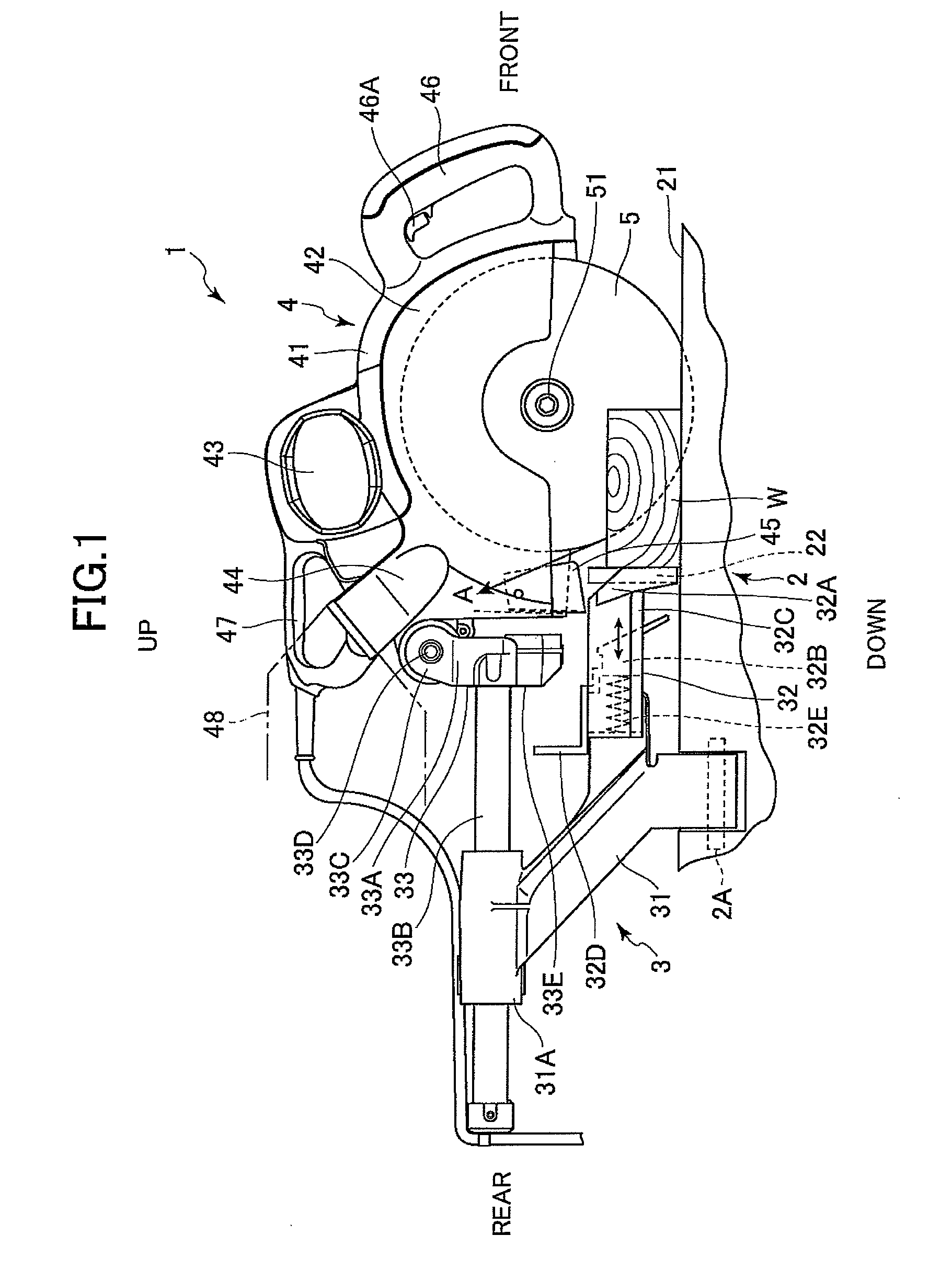
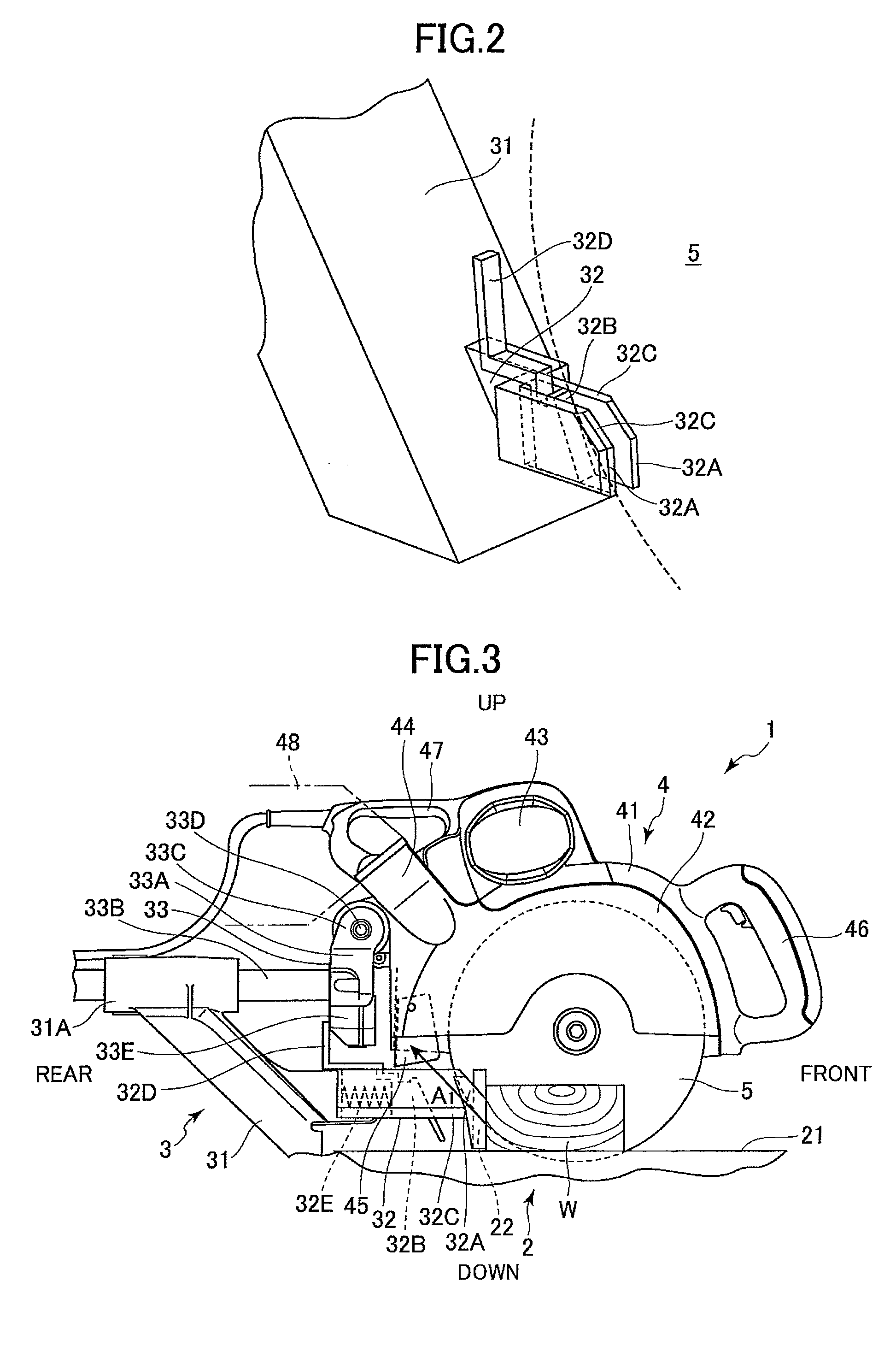
[0016]A miter saw according to an embodiment of the present invention will now be described with reference to FIGS. 1 to 4. A miter saw 1 has a slide mechanism and includes mainly a base section 2, a support section 3, and a cutting section 4.

[0017]The base section 2 is configured to include an upper face 21 and a pin 2A connecting with the support section 3. The upper face 21 supports a wooden material W as a workpiece to be cut. The pin 2A has its own axis extending in parallel with the upper face 21. One axial side of the pin 2A where the workpiece W is set will be referred to as a front side. An opposite side to the front side will be referred to as a rear side. A side of the cutting section 4 will be referred to as an upper side, and a side of the base section 2 will be referred to as a lower side. A groove extends in the frontward / rearward direction is formed in the upper face 21 for allowing a part of a circular saw blade 5 (described later) to be inserted thereinto.

[0018]A p...


PUM

PropertyMeasurementUnit
heightaaaaaaaaaa
inclination angleaaaaaaaaaa
areaaaaaaaaaaa

Abstract

A miter saw capable of reducing scattering amount of cutting chips at a terminal phase of cutting operation. The miter saw includes a base section for supporting a workpiece, a cutting section, and a support section for supporting the cutting section. The support section includes a slide support part extending from the base section, and a pivot support part for pivotally movably supporting the cutting section. The cutting section includes a cutting chip inflow part. A guard extends from the slide support part. The guard has a slope portion for guiding cutting chips toward the inflow part. The slope portion is positioned on an extension of an intersection line defined between the base section and a saw blade and is movable in the direction of the intersection line.

Description

BACKGROUND OF THE INVENTION[0001]The present invention relates to a miter saw, and more particularly, to a miter saw having a slide mechanism.[0002]In a conventional miter saw having a slide mechanism, an exhaust port is provided behind a saw blade so as to allow cutting chips to flow into the port and to be discharged outside through the port. A dust collector, or a dust collector bag, and the like are connected to the exhaust port to collect cutting chips into the dust collector bag. In order to raise dust collection efficiency, laid-open Japanese Utility Model application publication Nos. H3-108401 and H3-112301 disclose a mechanism for moving a guide plate for guiding cutting chips to an exhaust port. The guide plate is provided at a lower part of a miter saw body and has a substantially U-shaped cross-section. The guide plate is pivotally movable. In case a workpiece to be cut has a certain height, the guide plate is elevated in contact with the workpiece.[0003]Laid-open Japane...

Claims


Application Information

Patent Timeline
Patent Type & Authority Applications(United States)
IPC IPC(8): B26D1/18
CPCB23D59/006B23D45/048Y10T83/7763Y10T83/7793Y10T83/7697
Inventor NISHIKAWA, TOMOMASAMATSUNAGA, KENICHI
Owner KOKI HLDG CO LTD
Why Eureka
Try Eureka