Variable resistance pulmonary ventilation bypass valve

a pulmonary ventilation and valve technology, applied in the field of diseased lungs, can solve the problems of individuals who may find it somewhat more difficult to carry on certain activities or bodily responses requiring airflow through the native airways, and achieve the effects of reducing or substantially reducing trapped air, facilitating air flow, and increasing air pressure in the lungs

Inactive Publication Date: 2007-07-19
PORTAERO
View PDF99 Cites 49 Cited by
  • Summary
  • Abstract
  • Description
  • Claims
  • Application Information

AI Technical Summary

Benefits of technology

[0017] The collateral ventilation bypass systems described herein provide a means for eliminating or substantially reducing trapped air in the lung or lungs by facilitating the flow of air via alternate pathways created through the pleura of the lung or lungs. However, by redirecting normal airflow through alternate passageways, the individual may find it somewhat more difficult to carry on certain activities or bodily responses requiring airflow through the native airways, i.e. the trachea. These activities and bodily responses may include speaking, coughing and throat clearing.
[0018] The present invention is directed to the incorporation of a flow restrictor device or valve assembly for controlling the flow of air through the conduits of the collateral ventilation bypass system of the present invention. By controlling the airflow through the bypass system, increased air pressure in the lungs may be achieved so that additional air may be forced to flow or travel through the native airways. With this increase in pressure and additional air volume, the individual may be able to speak more easily by forcing more air to flow past the vocal chords, to cough and to clear his or her throat. In addition, an increase in pressure within the lung or lungs may increase gas exchange, thereby making the lung or lungs more efficient. Also, by utilizing a flow restrictor device or valve assembly to restrict or temporarily block the flow of air through the bypass system, the native air passages may be utilized more and thus remain healthy, operational and effective.

Problems solved by technology

However, by redirecting normal airflow through alternate passageways, the individual may find it somewhat more difficult to carry on certain activities or bodily responses requiring airflow through the native airways, i.e. the trachea.

Method used


Image

  • Variable resistance pulmonary ventilation bypass valve
  • Variable resistance pulmonary ventilation bypass valve
  • Variable resistance pulmonary ventilation bypass valve

Examples


Embodiment Construction

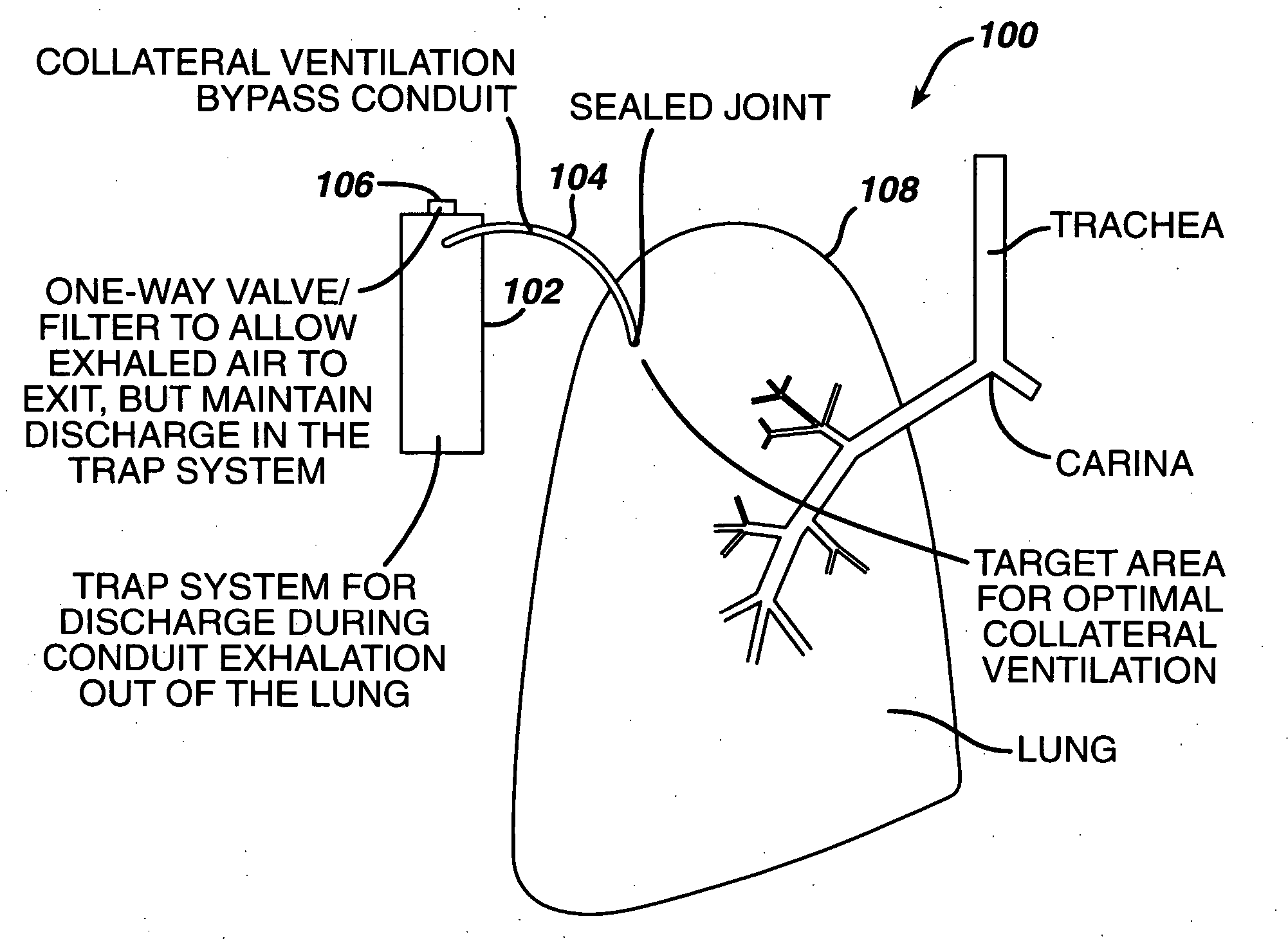
[0033] Air typically enters the mammalian body through the nostrils and flows into the nasal cavities. As the air passes through the nostrils and nasal cavities, it is filtered, moistened and raised or lowered to approximately body temperature. The back of the nasal cavities is continuous with the pharynx (throat region); therefore, air may reach the pharynx from the nasal cavities or from the mouth. Accordingly, if equipped, the mammal may breath through its nose or mouth. Generally air from the mouth is not as filtered or temperature regulated as air from the nostrils. The air in the pharynx flows from an opening in the floor of the pharynx and into the larynx (voice box). The epiglottis automatically closes off the larynx during swallowing so that solids and / or liquids enter the esophagus rather than the lower air passageways or airways. From the larynx, the air passes into the trachea, which divides into two branches, referred to as the bronchi. The bronchi are connected to the ...


PUM


Abstract

A collateral ventilation bypass trap system directly linked with a patient's lung or lungs may be utilized to increase the expiratory flow from the diseased lung or lungs, thereby treating one aspect of chronic obstructive pulmonary disease. The system includes a trap, a filter/one-way valve, an air carrying conduit and a retention device for securing system elements in position. The system also includes a flow restriction device for controlling the flow of air through the air carrying conduit.

Description

BACKGROUND OF THE INVENTION [0001] 1. Field of the Invention [0002] The present invention relates to devices for treating diseased lungs, and more particularly, to a device for controlling the flow of air being vented from predetermined sites in the lung or lungs. [0003] 2. Discussion of the Related Art [0004] As a result of studies that date back to the 1930's and particularly studies conducted in the 1960's and early 1970's, it has been determined that long-term continuous oxygen therapy is beneficial in the treatment of hypoxemic patients with chronic obstructive pulmonary disease. In other words, a patient's life and quality of life can be improved by providing a constant supplemental supply of oxygen to the patient's lungs. [0005] However, with the desire to contain medical costs, there is a growing concern that the additional cost of providing continuous oxygen therapy for chronic lung disease will create an excessive increase in the annual cost of oxygen therapy. Thus, it is ...

Claims


Application Information

Patent Timeline
Patent Type & Authority Applications(United States)
IPC IPC(8): A62B9/06A61M16/00A62B9/02
CPCA61M1/008A61M16/00A61M16/009A61M16/0434A61M16/0463A61M16/107A61M39/0247A61M2210/101A61M2210/1039A61M16/0406A61M16/0459A61M16/208A61M16/022A61M1/84
Inventor CHANG, ASIATANAKA, DON AKIRA
Owner PORTAERO
Why Eureka
Try Eureka