Processing method and processing device

a processing method and processing device technology, applied in manipulators, gripping heads, metabolism disorders, etc., can solve the problems of inability to clamp body parts on the inside, limited access to components of external welding robots or the like, etc., and achieve the effect of better machining techniques

Inactive Publication Date: 2007-07-19
KUKA SYSTEMS
View PDF14 Cites 19 Cited by
  • Summary
  • Abstract
  • Description
  • Claims
  • Application Information

AI Technical Summary

Benefits of technology

[0004] The object of the present invention is to show a better machining technique.

Problems solved by technology

Moreover, the accessibility of the components for external welding robots or the like is limited.
Clamping body parts on the inside is not possible.

Method used


Image

  • Processing method and processing device
  • Processing method and processing device
  • Processing method and processing device

Examples


Embodiment Construction

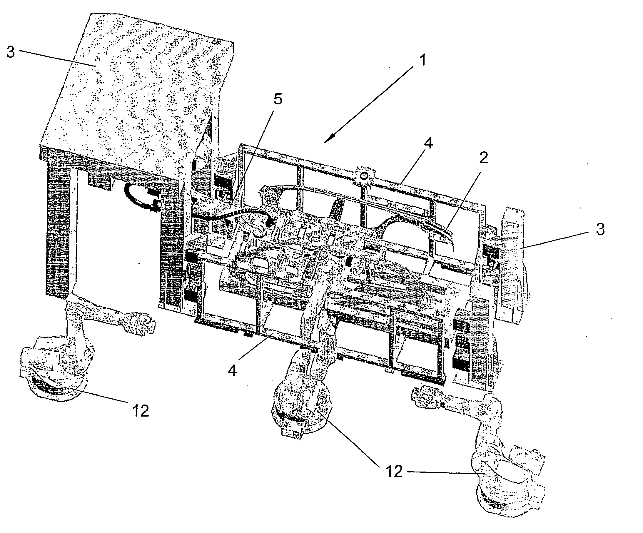
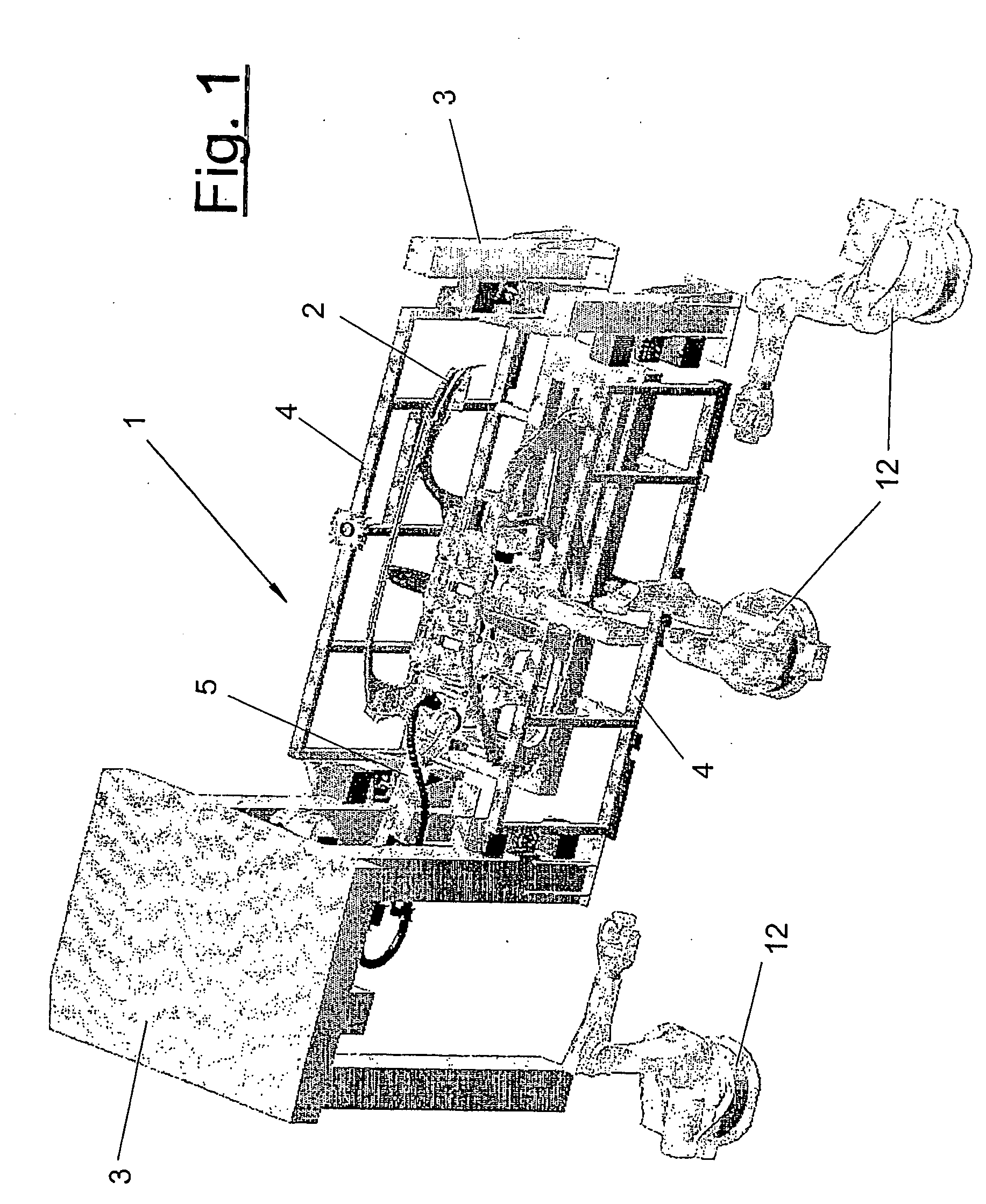
[0021] Referring to the drawings in particular, FIG. 1 shows a machining station (1) for components (2), which station may have any desired suitable design. In the exemplary embodiment being shown, it is a geo station or framing station for body parts (2), for example, side panels and floor group, which are brought into the machining station (1) on a pallet or another suitable carrier by means of a conveyor, not shown, and positioned here exactly in a position suitable for machining. The machining station (1) may be part of a larger production plant and integrated in this case within a transfer line formed by a plurality of stations.

[0022] One or more external clamping frames (4), for example, the two side frames shown in FIG. 1, which are docked with the station frame (3) or alternatively with the pallet in a suitable and accurately positioned manner, may be present in the machining station (1) for clamping the body parts (2).

[0023] A plurality of machining devices (5, 12) are pr...


PUM

PropertyMeasurementUnit
heightaaaaaaaaaa
shapeaaaaaaaaaa
flexibleaaaaaaaaaa

Abstract

A processing device (5) is provided for automobile body parts (2). The device (5) includes a multiaxial conveying robot (6) on which at least one support or carrier (7) is disposed. The at least one support (7) is provided with one or several multiaxial processing units, preferably small robots (10). The small robots (10) support different tools and can be controlled individually.

Description

CROSS REFERENCE TO RELATED APPLICATIONS [0001] This application is a United States National Phase application of International Application PCT / EP2004 / 003836 of Apr. 17, 2004 that claims the benefit of priority of German Application 203 06 257.4 filed Apr. 10, 2003, the entire contents of each application are incorporated herein by reference.FIELD OF THE INVENTION [0002] The present invention pertains to a machining method and a machining device for components, especially motor vehicle body parts. BACKGROUND OF THE INVENTION [0003] Such machining devices are known from practice, e.g., as welding robots. They comprise a multiaxial transport means in the form of an articulated arm robot and a tool, e.g., a welding tool. Furthermore, it is known from practice in the case of machining stations for body parts, especially so-called geo stations or framing stations for tacking the body parts, that stationary or mobile lateral clamping frames, which may be equipped with a plurality of clampi...

Claims


Application Information

Patent Timeline
Patent Type & Authority Applications(United States)
IPC IPC(8): B21J13/08A61P3/10B23Q39/02B25J15/00C07D207/16
CPCB23Q39/026B25J15/0061C07D207/16B25J15/0052A61P3/10
Inventor HESSE, JOHANN
Owner KUKA SYSTEMS
Why Eureka
Try Eureka