Automatic exposure system for imaging-based bar code reader

an exposure system and bar code reader technology, applied in the field of automatic exposure system for imaging-based bar code readers, can solve the problems of time-consuming iterative procedure to determine an acceptable integration time-gain factor product, exacerbate the delay in successful imaging and decoding, and inability to accurately determine the proper integration time and gain factor, etc., to achieve the effect of reducing the tim

Inactive Publication Date: 2007-07-19
SYMBOL TECH INC
View PDF16 Cites 77 Cited by
  • Summary
  • Abstract
  • Description
  • Claims
  • Application Information

AI Technical Summary

Benefits of technology

[0012] The imaging system includes a 2D pixel array and a focusing lens to focus reflected light from the target object onto the pixel array. The imaging system further includes an automatic exposure system for determining an integration or exposure time as to reduce the time required to capture a decodable image of the target object. The integration time is a time during which the reflected light from the target object is focused onto the pixel array and the pixel array is in a state such that the pixels receive the reflected light and accumulate an electrical charge the magnitude of which depends on the intensity of the light focused on the individual pixels.

Problems solved by technology

Because the intensity of the reflected light projected onto the pixel array varies with a distance between the target object and the imaging assembly, determination of a proper integration time and gain factor is not a simple task.
Such an iterative procedure to determine an acceptable integration time-gain factor product is time consuming.
Moreover, if the entire pixel array is read out for each successive image frame, the delay in successful imaging and decoding is exacerbated.
Read time differences of around 10 ms can result in measurable differences in productivity.

Method used


Image

  • Automatic exposure system for imaging-based bar code reader
  • Automatic exposure system for imaging-based bar code reader
  • Automatic exposure system for imaging-based bar code reader

Examples


Embodiment Construction

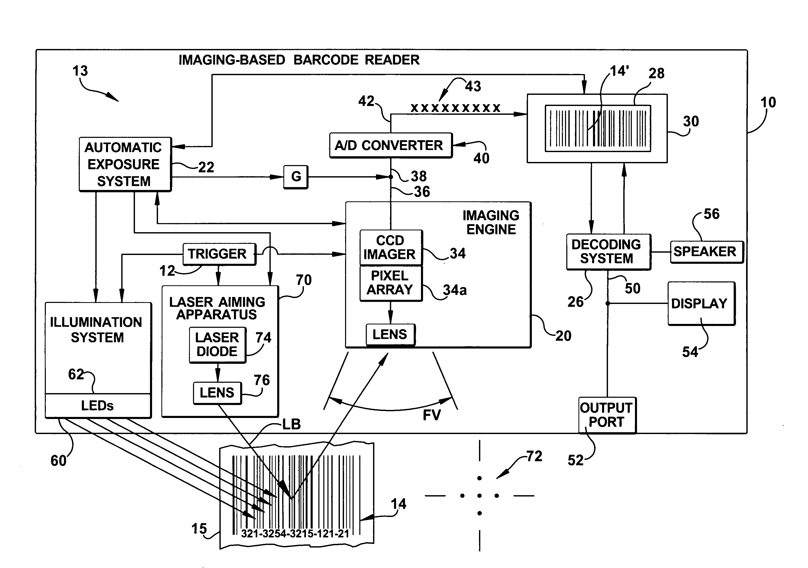
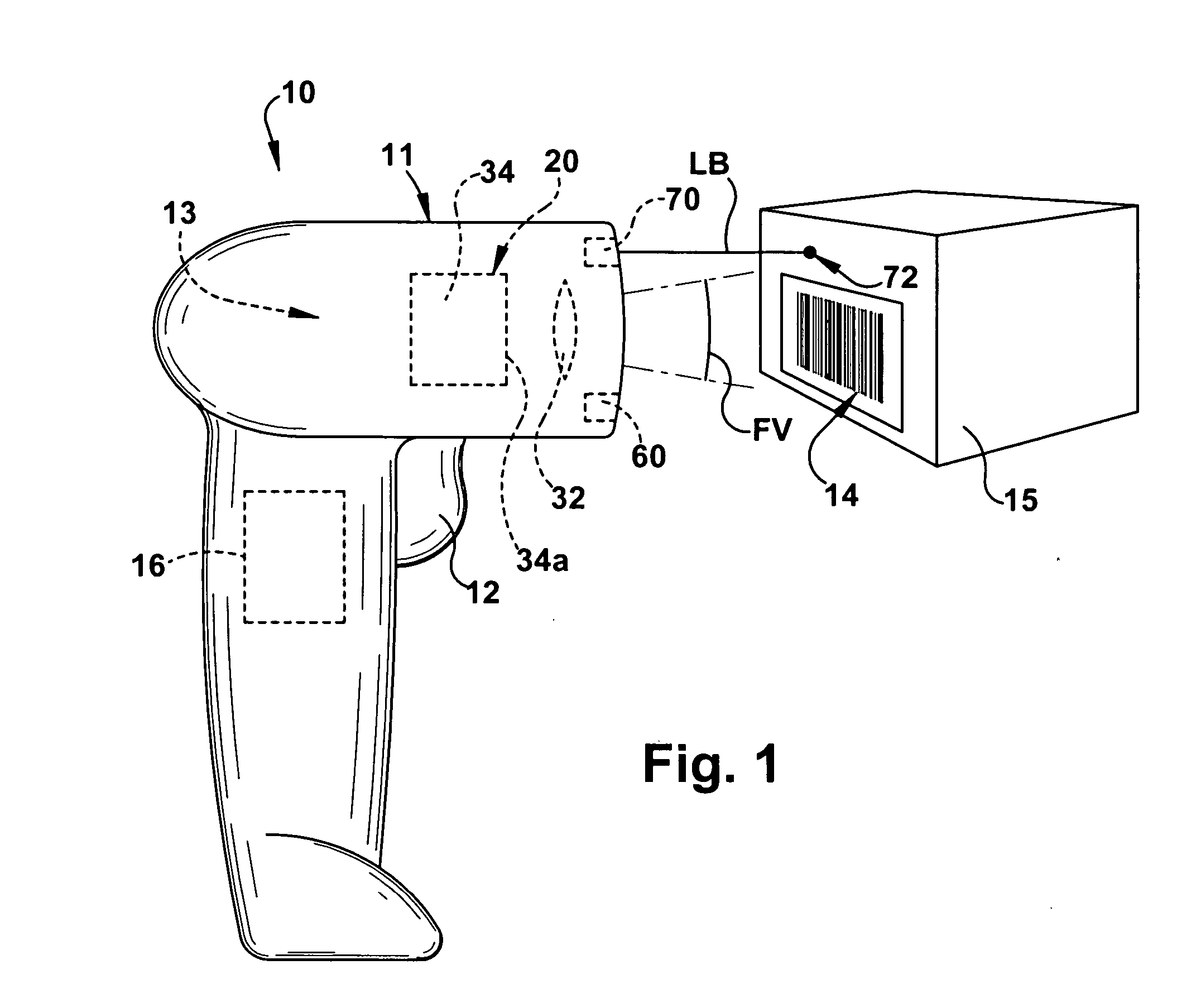
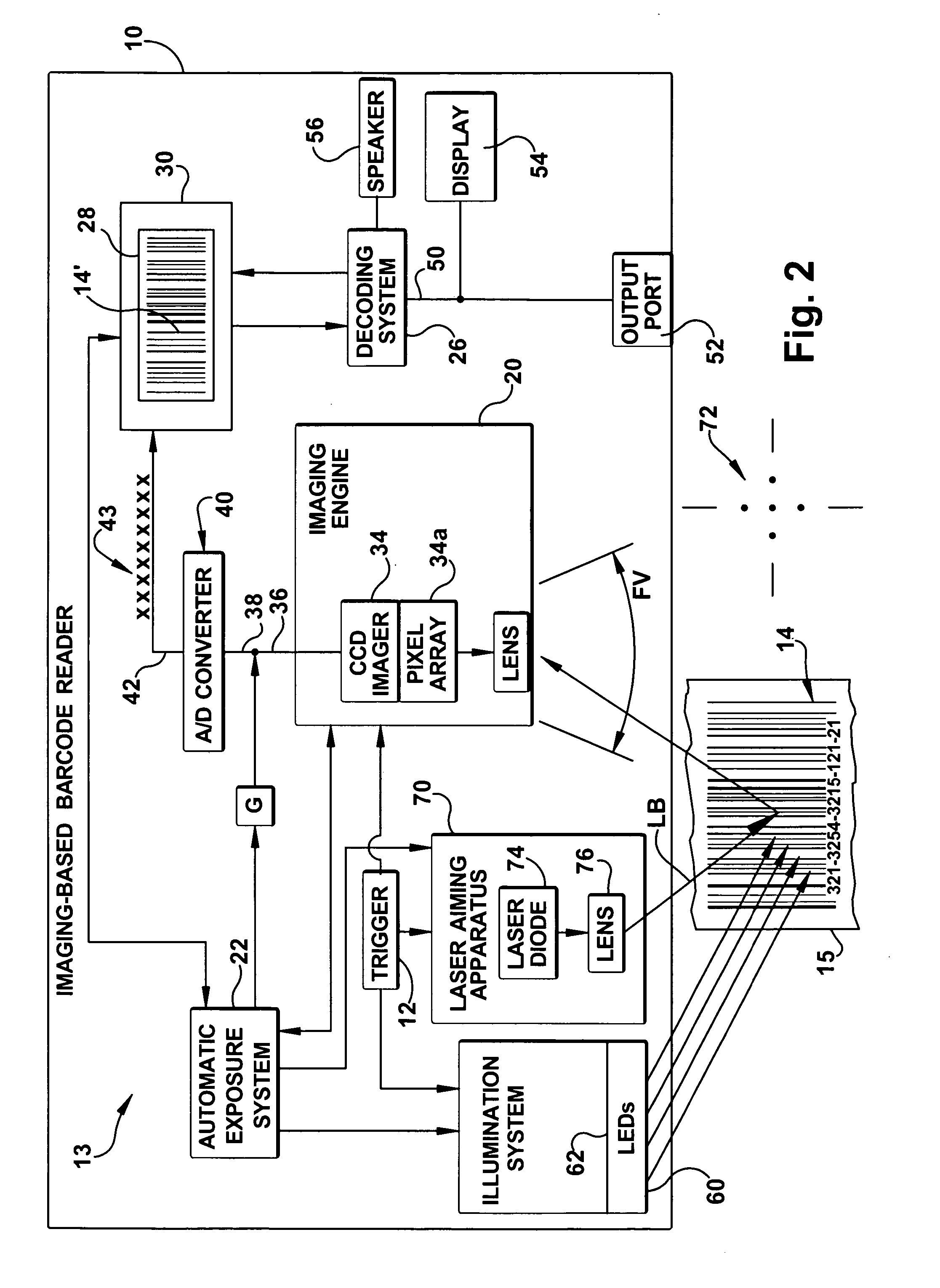
[0029] An imaging-based reader, such as an imaging-based bar code reader, is shown schematically at 10 in FIG. 1. The bar code reader 10, in addition to imaging and decoding both 1D and 2D bar codes and postal codes, is also capable of capturing images and signatures. The bar code reader 10 includes an imaging system or engine 20 for imaging and decoding captured images and features an automatic exposure system 22, to be described below.

[0030] In one preferred embodiment of the present invention, the bar code reader 10 is a hand held portable reader encased in a pistol-shaped housing 11 adapted to be carried and used by a user walking or riding through a store, warehouse or plant for reading bar codes for stocking and inventory control purposes. However, it should be recognized that the automatic exposure system 22 of the present invention may be advantageously used in connection with any type of imaging-based automatic identification system including, but not limited to, bar code ...


PUM


Abstract

An automatic exposure system for an imaging-based bar code reader. The automatic identification system includes: an aiming apparatus generating a beam to aid in aiming the system at a target object when the system is actuated; an imaging system including a pixel array, a focusing lens to focus an image of the target object onto the pixel array; and an automatic exposure system to determine an integration time for capturing an image of the target object. The automatic exposure system determines an integration time by: projecting an aiming pattern on the target object and capturing an image of the aiming pattern; determining a target distance from the imaging system to the target object based on a location of the aiming pattern within the captured image; determining a gain-integration time product utilizing an equation wherein the gain-integration time product is a function of a predetermined target image brightness and the target distance; and determining the integration time by selecting a gain value and solving for integration time given the gain-integration time product.

Description

FIELD OF THE INVENTION [0001] The present invention relates to an automatic exposure system for an imaging-based bar code reader. BACKGROUND OF THE INVENTION [0002] Various electro-optical systems have been developed for reading optical indicia, such as bar codes. A bar code is a coded pattern of graphical indicia comprised of a series of bars and spaces of varying widths, the bars and spaces having differing light reflecting characteristics. The pattern of the bars and spaces encode information. Systems that read and decode bar codes employing imaging systems are typically referred to as imaging-based bar code readers or bar code scanners. [0003] Imaging systems include charge coupled device (CCD) arrays, complementary metal oxide semiconductor (CMOS) arrays, or other imaging pixel arrays having a plurality of photosensitive elements or pixels. An illumination system comprising light emitting diodes (LEDs) or other light source directs illumination toward a target object, e.g., a t...

Claims


Application Information

Patent Timeline
Patent Type & Authority Applications(United States)
IPC IPC(8): G06K7/10G06K9/24
CPCG06K7/10752G06K7/10722
Inventor JOSEPH, EUGENECARLSON, BRADLEY S.
Owner SYMBOL TECH INC
Why Eureka
Try Eureka