Firefighting fluid delivery system

Inactive Publication Date: 2007-07-19
ELKHART BRASS MFG
View PDF19 Cites 34 Cited by
  • Summary
  • Abstract
  • Description
  • Claims
  • Application Information

AI Technical Summary

Benefits of technology

[0005] Accordingly, the present invention provides a fire fighting fluid delivery system that provides better control over the pressure of the fire fighting fl

Problems solved by technology

Consequently, optimal flow conditio

Method used


Image

  • Firefighting fluid delivery system
  • Firefighting fluid delivery system
  • Firefighting fluid delivery system

Examples


Embodiment Construction

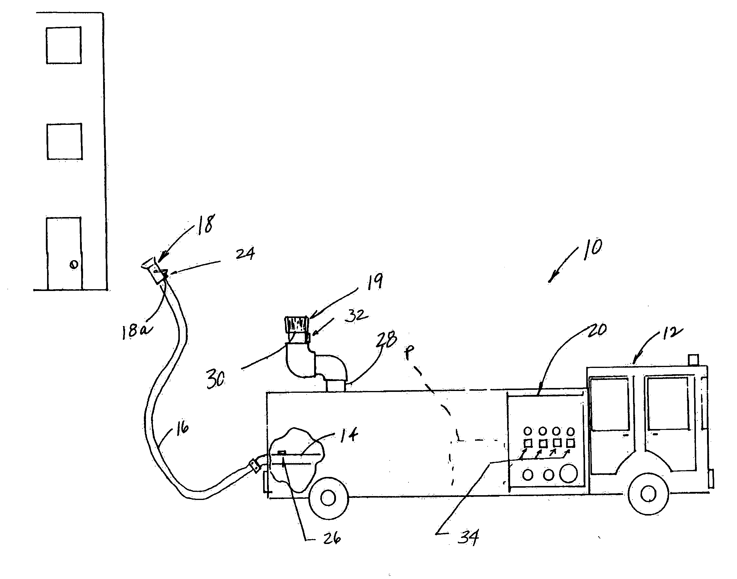
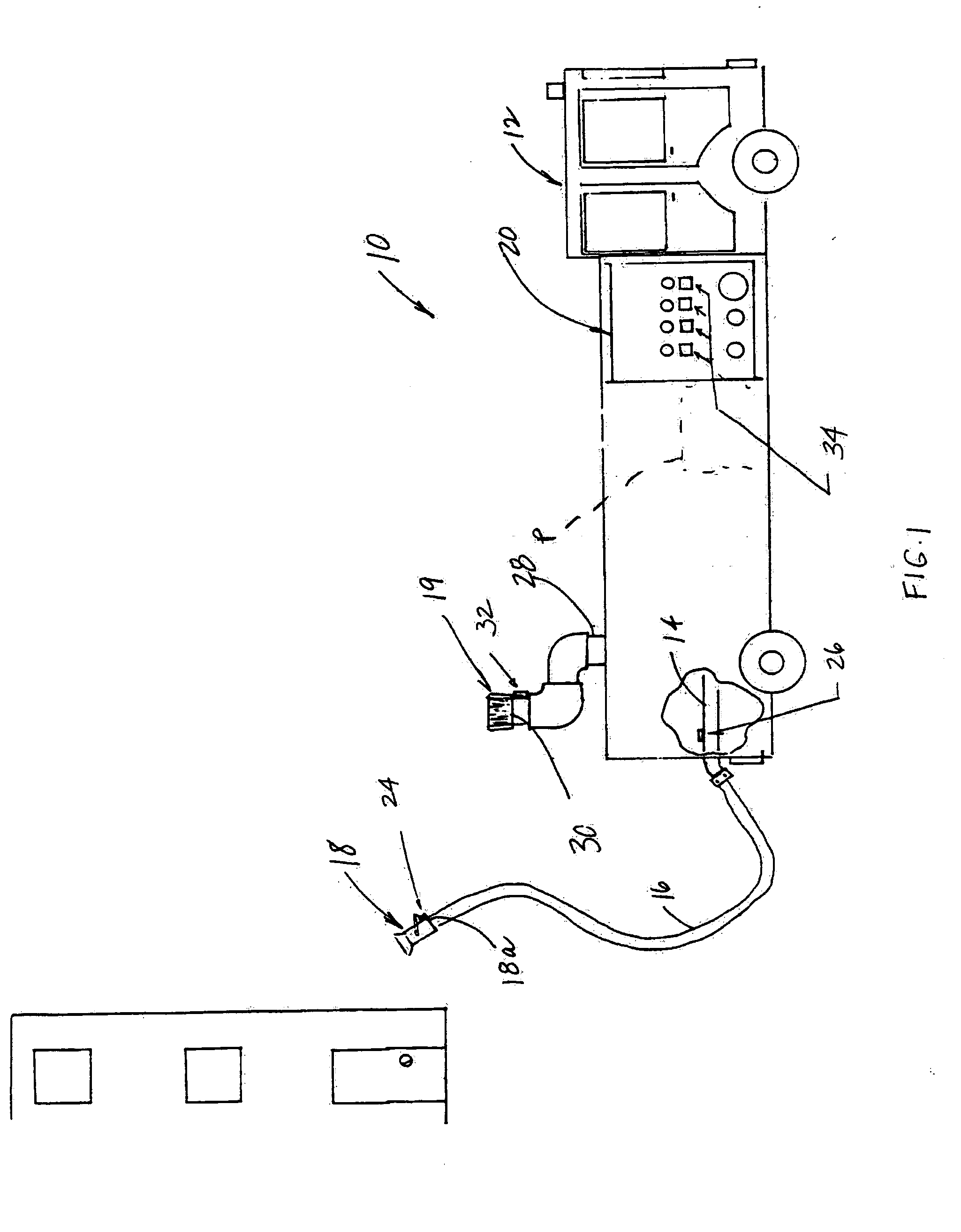
[0023] Referring to FIG. 1, the numeral 10 generally designates a fire fighting fluid system of the present invention. As will be more fully described below, system 10 provides enhanced control over of the delivery of fire fighting fluid and allows for one or more parameters of the fluid to be monitored, such as pressure, flow rate, temperature, or the like, as well as parameters of the system components, such as a fire truck's engine speed (RPM) to thereby provide enhanced management of the fire fighting fluid. Control is achieved by using a feedback control loop that allows one or more fluid parameters to be monitored at one or more specific points of interest, such as at a fire fighting delivery device, such as a nozzle, especially a nozzle inlet, a monitor, a truck outlet connection, a pipe, or a valve, for example.

[0024] In the illustrated embodiment, system 10 is incorporated in a fire truck 12, which includes a fire truck outlet 14, which is in fluid communication with the t...


PUM


Abstract

A fire fighting fluid delivery system includes a fire fighting fluid delivery device, a pressure sensor, which senses fluid pressure at the fluid delivery device and generates a pressure signal indicative of the fluid pressure, and a wireless transmitter for transmitting the pressure signal. The fluid delivery system further includes a fire fighting fluid input device which is in fluid communication with the fluid delivery device and a wireless receiver that receives the pressure signal. In addition, the system includes a pressure gauge in communication with the receiver, which displays a pressure reading based on the pressure signal received by the receiver wherein a pump operator may selectively adjust the delivery of fluid to the fluid delivery device from the fluid input device based on the pressure reading displayed at the pressure gauge.

Description

[0001] The present application claims the benefit of U.S. provisional application Ser. No. 60 / 748,557 for FIRE FIGHTING FLUID DELIVERY SYSTEM, filed on Dec. 8, 2005, which is incorporated by reference herein in its entirety.TECHNICAL FIELD AND BACKGROUND OF THE INVENTION [0002] The present invention generally relates to a fire fighting fluid delivery system and, more particularly, to a control system for controlling the flow of fire fighting fluid from a fluid delivery device of a fire fighting fluid delivery system, such as a nozzle, monitor, fire truck outlet or the like. [0003] Successful fire fighting is dependent on the adequate application of water to a fire. Many factors effect adequate water application—two specifically important aspects are technique and quantity of water. All fire fighting products depend on the direct correlation of water pressure and flow orifice at the delivery device (nozzle, monitor, etc) to determine the flow rate of water delivered. One of the most ...

Claims


Application Information

Patent Timeline
IPC IPC(8): A62C31/00A62C27/00A62C37/08F17D3/01
CPCA62C31/00A62C37/36A62C37/08Y10T137/6881Y10T137/8175Y10T137/8326
Inventor LOZIER, TODD BRIANJONES, LEE R.
Owner ELKHART BRASS MFG
Why Eureka
Try Eureka