
Ink jet recording apparatus

Inactive Publication Date: 2007-07-19
FUJIFILM CORP
View PDF4 Cites 23 Cited by
  • Summary
  • Abstract
  • Description
  • Claims
  • Application Information

AI Technical Summary

Benefits of technology

[0009]The purpose of the present invention is to solve the problems of the above conventional techniques, and to provide an ink jet recording apparatus for performing image recording on a sheet type of recording paper, capable of keeping the distance between a recording sheet and a recording head constant at an image recording section where image recording is performed by a recording head by steadily holding the entire area of the recording sheet including the edges thereof on the platen, thus, capable of recording an image with high quality on the entire surface of the recording sheet, and also capable of performing image recording without a margin (i.e., borderless printing) avoiding contamination of a transport path or the platen.
[0019]According to the present invention, in the image recording section where the image recording is performed by the recording head, it is possible to keep the distance between the recording head and the recording sheet about the entire area including the edges constant by steadily holding the entire area of the recording sheet including the edges on the platen. Thus, it is possible to perform the image recording with high quality on the entire surface of the recording sheet, and perform borderless printing without contaminating the transport path or the platen.

Problems solved by technology

However, the front edge of the recording sheet is not held during the image recording, so floating of the front edge of the recording sheet due to the curl thereof cannot be suppressed.
Therefore, the distance between a recording head and the recording sheet cannot be constant, which leads to degradation of image quality of an image recorded.

Method used


Image

  • Ink jet recording apparatus
  • Ink jet recording apparatus
  • Ink jet recording apparatus

Examples


Embodiment Construction

[0027]An ink jet recording apparatus according to the present invention is explained in detail referring to preferred embodiments shown in the attached drawings.

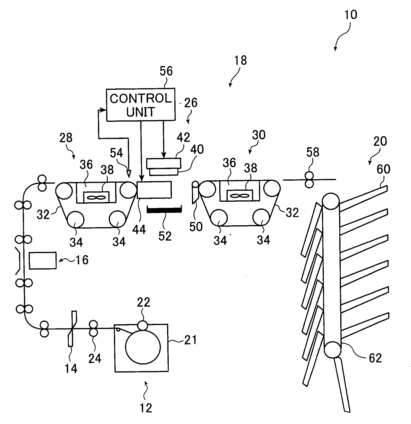
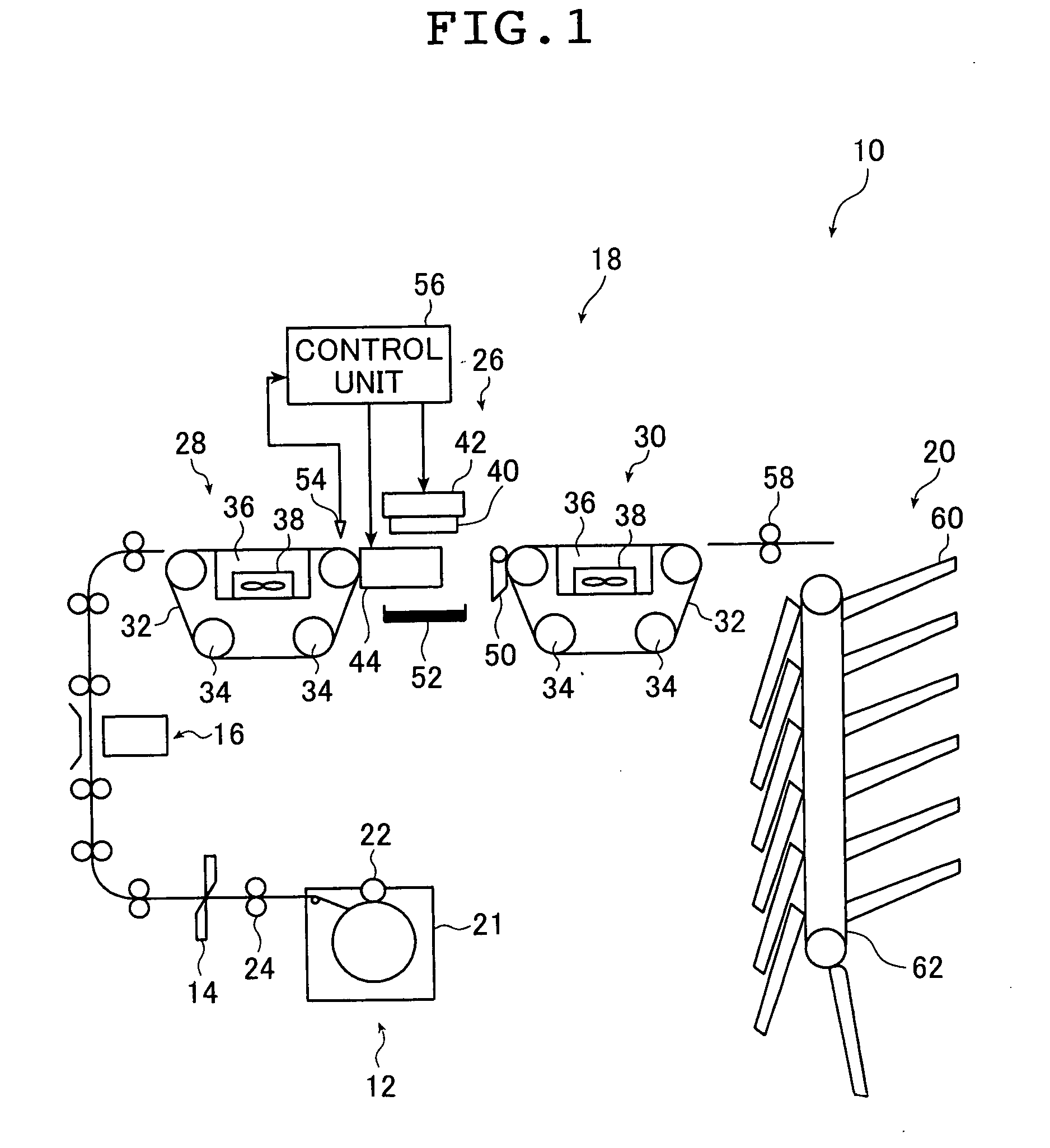
[0028]FIG. 1 is a block diagram showing a schematic configuration of one embodiment of the ink jet recording apparatus according to the present invention. In a printer 10 shown in FIG. 1, rolled recording paper is cut prior to image recording to prepare a cut recording sheet A having a predetermined print size, and the image recording is performed by the ink jet system on the entire surface of the recording sheet A, whereby a borderless print is produced and outputted.

[0029]The printer 10 includes a paper supplying section 12, a cutter 14, a back-printing unit 16, an image recording section 18, a sorter 20, and transport means for transporting the recording sheet A to each section through a predetermined path. In addition to the components shown in the figure, the printer 10 may comprise various components included in the pu...


PUM


Abstract

There are provided an ink jet recording apparatus which includes an ink jet recording head; an upstream side transport unit arranged upstream of a recording position; a downstream side transport unit arranged downstream of the recording position; a platen arranged to be spaced apart from the ink jet recording head by a predetermined interval necessary for image recording, the platen being movable in a transport direction of the recording sheet between the upstream side transport unit and the downstream side transport unit; a control unit controlling a movement of the platen; and an ink receiver arranged to face the ink jet recording head across an ink ejection region of the ink jet recording head, the ink receiver receiving ink that was ejected from the ink jet recording head and passed across a position where the platen does not exist.

Description

[0001]The entire contents of the document cited in this specification are herein incorporated by reference.BACKGROUND OF THE INVENTION[0002]This invention belongs to the technical field of an ink jet recording apparatus, and more particularly relates to an ink jet recording apparatus capable of recording an image on the entire surface of a recording sheet without leaving a margin.[0003]In various image recording apparatuses for recording an image on a recording paper and outputting the recorded paper, especially in the case of an image recording apparatus for business purposes in which a large amount of paper is used, the cost of supplying paper by a roll form is lower than that by a cut-sheet form. For example, in ink jet printers for business purposes, a roll-paper loading type is popular. In the roll-paper loading type of the ink jet printer, roll paper is generally drawn and transported to a recording section in a continuous form as it is, and then cut into an output size after ...

Claims


Application Information

Patent Timeline
IPC IPC(8): B41J2/01
CPCB41J11/0065B41J11/06B41J11/0085B41J11/007
Inventor KITO, EIICHI
Owner FUJIFILM CORP
Learn More