Dispensing Blender Jar

a technology for blenders and jars, applied in the field of blender jars, can solve the problems of manual work that requires user attention, design may put extra strain on the blender motor, and effort also has limitations, so as to improve the horizontal flow of material, promote three-dimensional material flow, and improve the geometry of the blender jars

Active Publication Date: 2007-07-19
HAMILTON BEACH BRANDS
View PDF62 Cites 41 Cited by
  • Summary
  • Abstract
  • Description
  • Claims
  • Application Information

AI Technical Summary

Benefits of technology

[0010] Accordingly, it is an object of the present invention to improve blender jar geometry to promote three dimensional material flow. The jar would include a floor having an agitator. Alternatively, or in combination with an agitator, specific sidewall bumps may be used to improve the horizontal flow of material within a blender jar.

Problems solved by technology

While each is effective in improving performance in certain instances, these efforts also have their limitations.
However, if the blades move too fast, then the rapid rotation may cause cavitation.
If a user must manually vary the speed of operation of the blender, then such manual work requires user attention during some or all of the blending process.
If blade shape (including pitch and angle) is too aggressive, however, then the design may put extra strain on the blender motor.
If the blade shape is relatively flat, then it may be more prone to cavitation at high speeds of operation.
In any event, the cutter assembly cannot alone be used to overcome dead zones that are created in the material in a jar as a result of the processing inside a particular jar geometry.
Further, the triangular cross-section of the blender was not symmetrical as the third wall was longer than the first two walls.
However, the sidewall geometry only primarily affects the horizontal flow of material.
Therefore, the sidewall geometry is limited to essentially affecting only two dimensional change in material flow, i.e., in a single plane.
A common challenge for users of dispensing blenders is operating the blender to obtain a reasonable flow of material out of the blender.
Gravity is not always alone effective to achieve a reasonable flow of material from the blender jar.
Still further, the flow of material in a blender jar created through the action of a blender cutter may actually reduce or take away from the flow capabilities of the material from the blender jar.

Method used


Image

  • Dispensing Blender Jar
  • Dispensing Blender Jar
  • Dispensing Blender Jar

Examples


example 1

(FIGS. 1-4)

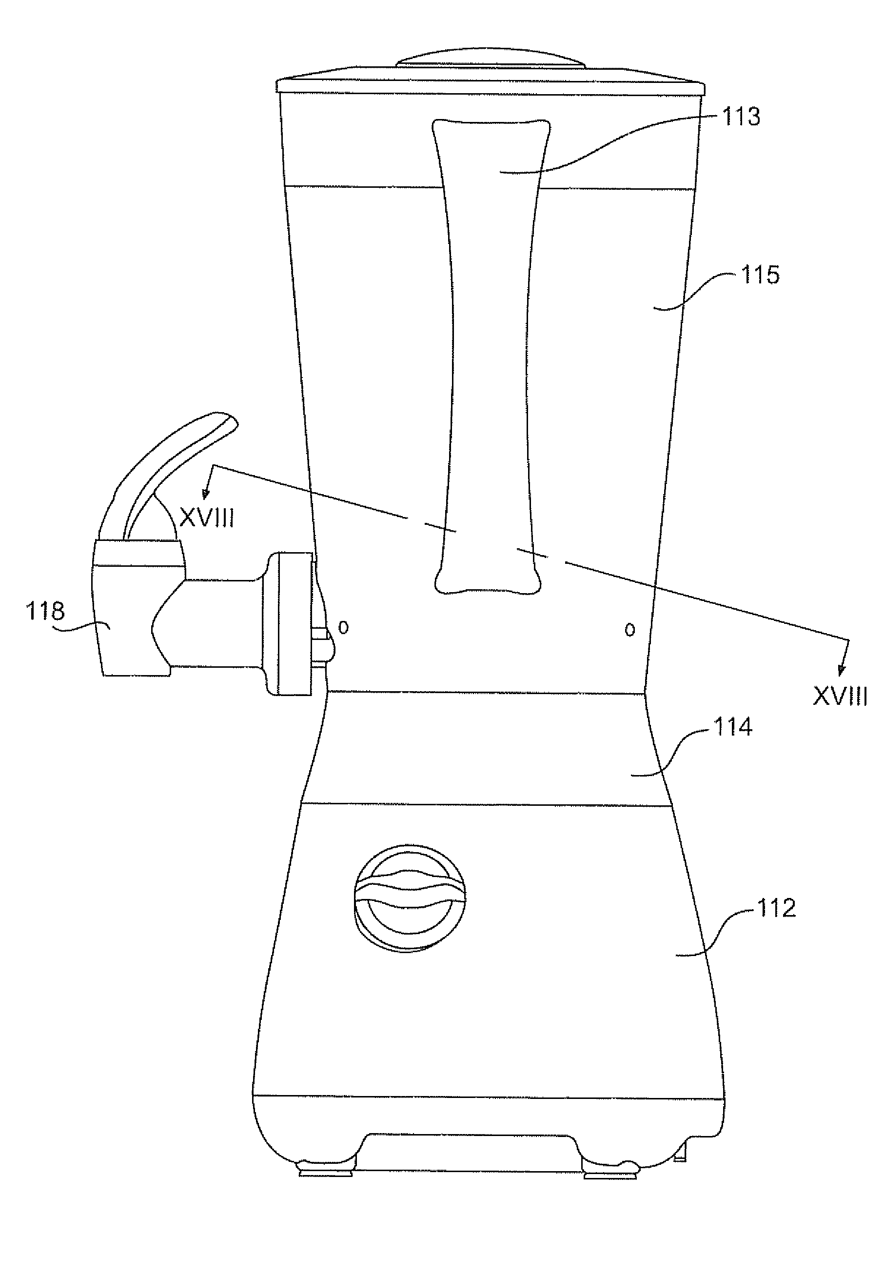
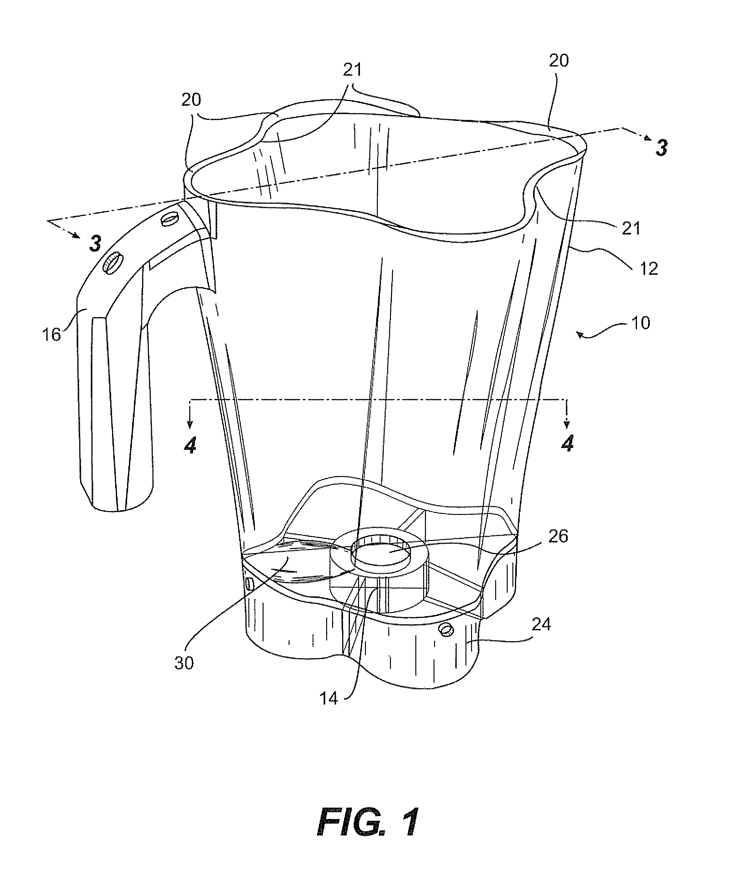
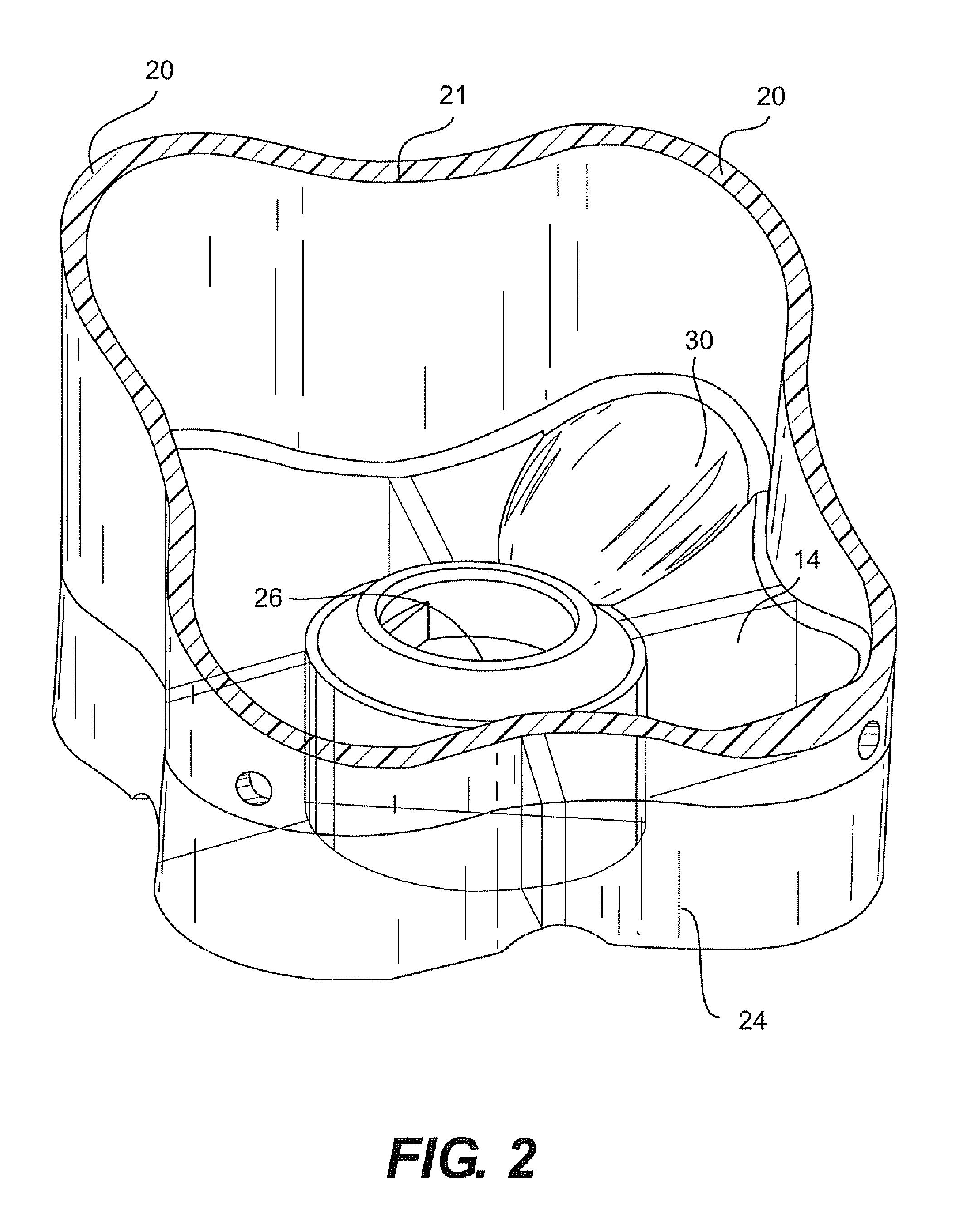
[0044]FIGS. 1-4 illustrate a substantially four-sided blender jar 10. The jar 10 has four sides 12 that make up the sidewall of the jar. The jar 10 has rounded vertical corners 20 and vertical bumps 21 along the vertical length of the jar. The floor 14 of the jar 10 is generally smooth and primarily embodies a revolve geometry to promote laminar flow in the circumferential direction on the floor during operation. The jar 10 includes a handle 16. The bottom portion 24 of the sidewalls 12 is adapted to be received in a blender base to secure the jar while the blender motor is operated to rotate a cutter assembly. The floor 14 also includes a central opening or aperture 26 through which extends a drive shaft 35. The drive shaft 35 has a cutter assembly 36 mounted onto it.

[0045] The floor 14 also includes an agitator in the form of a horizontal hump 30. The hump 30 is substantially the length of the radius of the jar from the central opening 26 to the sidewall 12. The heig...

example 2

(FIGS. 5-8)

[0048] Another example of a blender jar is shown in FIGS. 5-8. The jar 50 has a fundamentally round sidewall cross-section with two vertical bumps 53 on one side of the circular cross section. The floor 56 is curved in substantial part in a revolve geometry There is a handle 54. The bottom portion 58 of the sidewall 52 engages a blender base via the outside geometry of the jar (at the bumps) and a series of ribs and / or slots on the base of the, jar to hold the jar secure during operation.

[0049] The floor 56 includes multiple agitators, specifically, three surfaces 57 and 59 that disrupt laminar flow around the jar 50 in the circumferential direction. In this example, the pair of surfaces 57 are generally similar to each other. The surface 59 is similar in function the surfaces 57, but the surface 59 has slightly different geometry in that it is configured between the two bumps 53 and the sidewall 52. The surfaces 57 and 59 are substantially flat planes that are closer ...

example 3

(FIGS. 9-12)

[0053] A still further example of a blender jar is shown in FIGS. 9-12. Like the jar 50 shown in Example 2, jar 70 has a fundamentally round sidewall cross-section with two vertical bumps 73 on one side of the circular cross section. The floor 76 is curved in substantial part in a revolved geometry. There is a handle 74. The bottom portion 78 of the jar 70 engages a blender base to hold the jar secure during operation.

[0054] The floor 76 includes multiple agitators, specifically, three surfaces 77 and 79 that disrupt laminar flow around the jar 70 the circumferential direction. In this example, the pair of surfaces 77 are generally similar to each other. The surface 79 is similar in function to the surfaces 77, but the surface 79 has slightly different geometry in that it is configured between the two bumps 73 and the sidewalls 72. The surfaces 77 and 79 are substantially flat planes that are closer to the blades 80 and the blade path formed by the rotation of the bla...


PUM


Abstract

A blender jar defines a geometry to impart vertical movement to material being processed in the blender jar, and, alternatively or in combination, improves the horizontal movement to the blended material. By configuring one or more agitators on the floor of a jar, laminar flow or symmetric flow of material around the jar is disrupted. The material is forced in an upward direction in the jar and, therefore, into more frequent contact with the cutter blades rotating in the jar. A dispensing blender jar includes a hole in the jar wall that leads to a dispensing spout. The hole is positioned, at least in part, on the leading edge of a vertical bump in the sidewall of the jar.

Description

[0001] This application is a continuation in part of U.S. patent applications Ser. Nos. 11 / 052,338 and 11 / 051,573, each filed on Feb. 4, 2005 which are hereby incorporated by reference in their entirety.[0002] The present invention relates to a blender jar construction adapted to improve the blending performance of a blender. Specifically, the floor of the blender jar includes an agitator that imparts vertical movement to material that is being processed in the blender jar. Also, sidewall bumps are engineered relative to a blender blade path to improve performance. Still further, the sidewall bumps in combination with a channel leading to a dispensing spout, the channel open to the inside of the jar at the leading edge of a bump, improves the dispensing efficiency of a dispensing blender jar. BACKGROUND OF THE INVENTION [0003] Blender performance is the subject of considerable engineering by blender manufacturers. Efforts to improve blend consistency and efficiency have been directe...

Claims


Application Information

Patent Timeline
Patent Type & Authority Applications(United States)
IPC IPC(8): A47J43/046
CPCA47J43/0727A47J43/046
Inventor BRANSON, BENJAMIN HENRY IIIBOHANNON, JOHN ROBERT JR.WILLIAMS, BRIAN PAUL
Owner HAMILTON BEACH BRANDS
Why Eureka
Try Eureka