Method for rectifying stereoscopic display systems

a stereoscopic display and display system technology, applied in the field of stereoscopic capture, processing, and display systems, can solve the problems of reducing the ability of viewers to fuse, reducing the usefulness of stereoscopic display systems, and viewers being likely to experience visual fatigue and other undesirable side effects, so as to achieve the effect of minimizing spatial misalignmen

Inactive Publication Date: 2007-07-19
EASTMAN KODAK CO
View PDF11 Cites 102 Cited by
  • Summary
  • Abstract
  • Description
  • Claims
  • Application Information

AI Technical Summary

Benefits of technology

[0011] The present invention is directed to overcoming one or more of the problems set forth above. According to one aspect of the present invention, an image-processing algorithm is developed to correct the vertical misalignment introduced in the image capturing/producing process without prior knowledge of the causes. This image-processing algorithm compares the two images and registers one image to the other. The image registration process creates two displacement maps for both the horizontal and vertical directions. The algorithm applies the vertical displacement to one or both of the images t...

Problems solved by technology

Therefore, while horizontal disparities are expected, vertical disparities are not expected and can significantly degrade the usefulness of a stereoscopic display system.
For example, vertical displacement or misalignment existing between corresponding objects in the two images will reduce the viewer's ability to fuse the two images into a single perceive image, and the viewer is likely to experience visual fatigue and other undesirable side effects.
When the amount of misalignment is small, the presence of vertical disparity results in eyestrain, degraded depth, and partial loss of depth perception.
When the amount of vertical misalignment is large, vertical disparity may result in binocular rivalry and the total loss of depth perception.
Keystone distortion can also be created if the cameras are not positioned parallel to one another as is often required to capture objects that are close to the capture system.
This keystone distortion often reduces the vertical size of objects that are positioned at opposite sides of the scene, and this keystone distortion results in a vertical misalignment of a different amount for different pixels in the stereo pair.
The two captures can also have rotational or magnification differ...

Method used


Image

  • Method for rectifying stereoscopic display systems
  • Method for rectifying stereoscopic display systems
  • Method for rectifying stereoscopic display systems

Examples


Embodiment Construction

[0024] The present description is directed in particular to elements forming, part of, or cooperating more directly with, apparatus in accordance with the invention. It is to be understood that elements not specifically shown or described may take various forms well known to those skilled in the art.

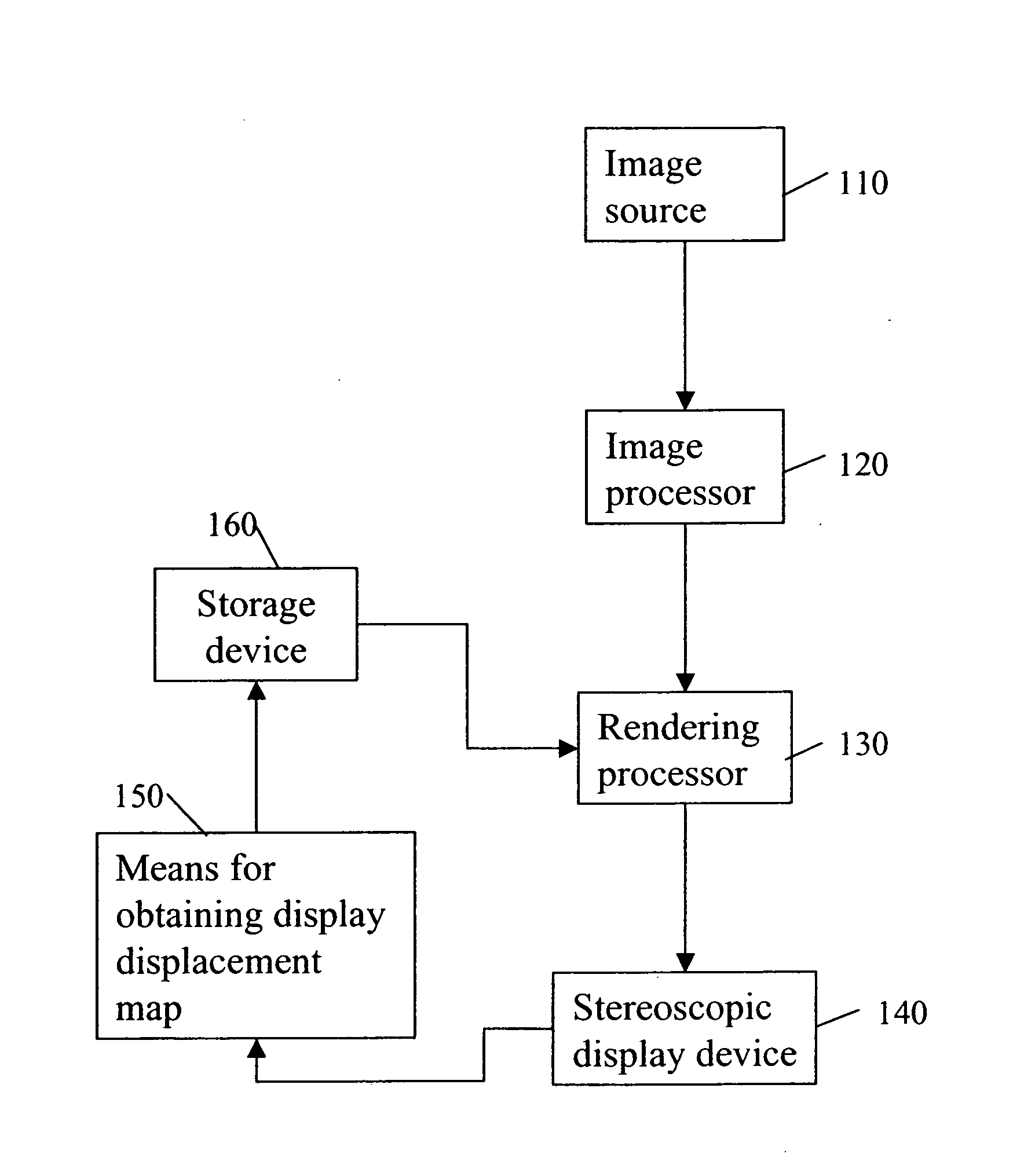
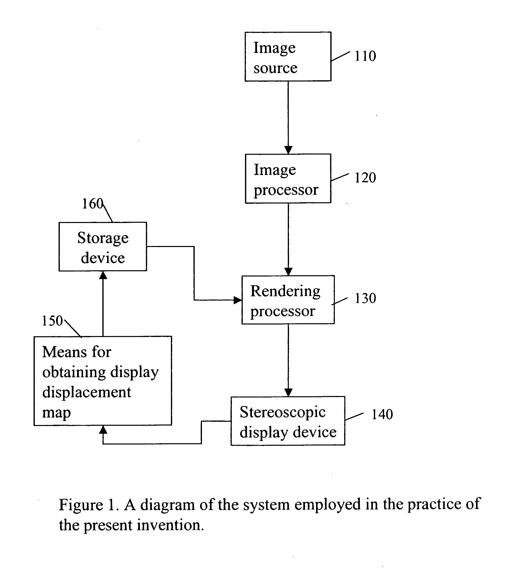
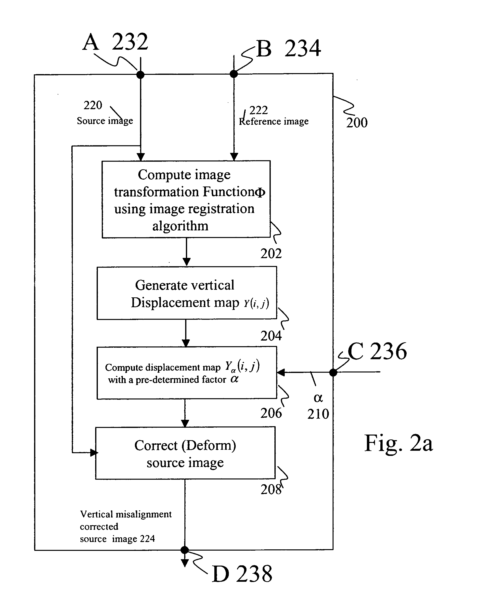
[0025] The present invention is directed towards a method for rectifying misalignment in a stereoscopic display system comprising: providing an input image to an image processor; creating an image source displacement map; obtaining a display displacement map; and applying the image source displacement map and the display displacement map to the input image to create a rectified stereoscopic image pair. The image source displacement map and the display displacement map may be combined to form a system displacement map and this map may be applied to the input image in a single step. Alternatively, the image source displacement map and the display displacement map may alternately be applie...


PUM


Abstract

A method for rectifying misalignment in a stereoscopic display system (140) comprises: providing a pair of input images to an image processor (120); creating an image source displacement map for the pair of input images; obtaining a display displacement map (150); and applying the image source displacement map and the display displacement map to the pair of input images to create a rectified stereoscopic image pair.

Description

FIELD OF THE INVENTION [0001] The invention relates generally to the field of stereoscopic capture, processing, and display systems. More specifically, the invention relates to a stereoscopic system that provides a way to compensate for spatial misalignment in source images and in the display system using image-processing algorithms. BACKGROUND OF THE INVENTION [0002] The normal human visual system provides two separate views of the world through our two eyes. Each eye has a horizontal field of view of about 60 degrees on the nasal side and 90 degrees on the temporal side. A person with two eyes, not only has an overall broader field of view, but also has two slightly different images formed at his / her two retinas, thus forming different viewing perspectives. In normal human binocular vision, the disparity between the two views of each object is used as a cue by the human brain to derive the relative depth between objects. This derivation is accomplished by comparing the relative ho...

Claims


Application Information

Patent Timeline
IPC IPC(8): G06K9/00H04N13/128
CPCH04N13/0018H04N13/0022H04N13/0425H04N13/02H04N13/0025H04N13/20H04N13/122H04N13/128H04N13/327H04N13/133H04N13/00
Inventor JIN, ELAINE W.MILLER, MICHAEL E.CHEN, SHOUPUBOLIN, MARK R.
Owner EASTMAN KODAK CO
Why Eureka
Try Eureka