Hydraulic control apparatus for an automatic transmission

a technology of hydraulic control apparatus and automatic transmission, which is applied in the direction of gearing control, gearing elements, gearing rings, etc., can solve the problems of inability to reverse the vehicle, and the reverse speed is not established

Inactive Publication Date: 2007-07-19
AISIN AW CO LTD +1
View PDF6 Cites 25 Cited by
  • Summary
  • Abstract
  • Description
  • Claims
  • Application Information

AI Technical Summary

Benefits of technology

[0009] Thus, one object of the present invention to provide a hydraulic control apparatus for an automatic transmission that enables establishing a reverse speed by switching a range switching valve to a reverse range position even when the solenoid valves that should be energized during reverse travel are de-energized.
[0010] According to a first aspect of the present invention, the first switching valve communicates a first engagement pressure to the first hydraulic servo by being locked in the normal position when the signal pressure of the signal pressure output solenoid valve is output, and even during a failure in which the first engagement pressure control solenoid valve and the signal pressure output solenoid valve are de-energized, when the range switching valve is switched to the reverse range position, the reverse range pressure is communicated to the first hydraulic servo by switching to the fail position due to the reverse range pressure. Thus, during normal operation, it is possible to establish smoothly the reverse speed by supplying the first engagement pressure, which is output from the first engagement pressure control solenoid valve, to the first hydraulic servo, and even during a failure, it is possible to establish the reverse speed by supplying the reverse range pressure to the first hydraulic servo, and thus the vehicle can travel in reverse even during a failure.
[0011] According to a second aspect of the present invention, the first switching valve includes a spool that is switched between a normal position and a fail position, an urging device that urges the spool toward the normal position, a first oil chamber in which the signal pressure of the signal pressure output solenoid valve acts on the spool in the direction of the normal position, and a second oil chamber in which the reverse range pressure acts on the spool in the direction of the fail position. Thus, the first switching valve is locked in the normal position when the signal pressure of the signal pressure output solenoid valve is output, and even during a failure, it is possible to switch the first switching valve to the fail position due to the reverse range pressure.
[0014] According to a fifth aspect of the present invention, during a failure in which the range position of the range switching valve is not detected by the range position detecting device, forward start control, in which the second engagement pressure control solenoid valve is energized, is carried out, and thus when the range switching valve is in the reverse range position, the forward speed is established, and it is possible for the vehicle to travel forward. In addition, when the range switching valve is in the reverse range position, while the second engagement pressure is not output from the second engagement pressure control solenoid valve when the reverse range pressure is not output and the establishment of the forward speed could be obstructed, the first switching valve is switched to the fail position by the reverse range pressure, it is possible to establish the reverse speed by supplying the reverse range pressure to the first hydraulic servo, and it is possible for the vehicle to travel in reverse.

Problems solved by technology

However, in the hydraulic control apparatus described above, when the solenoid valves that are necessary for establishing the reverse speed remain de-energized due to, for example, some sort of failure, there is a problem in that the reverse speed is not established, that is, the reverse travel of the vehicle becomes impossible.

Method used


Image

  • Hydraulic control apparatus for an automatic transmission
  • Hydraulic control apparatus for an automatic transmission
  • Hydraulic control apparatus for an automatic transmission

Examples


Embodiment Construction

[0022] Below, exemplary embodiments of the present invention will be explained with reference to FIG. 1 through FIG. 7.

Configuration of Automatic Transmission

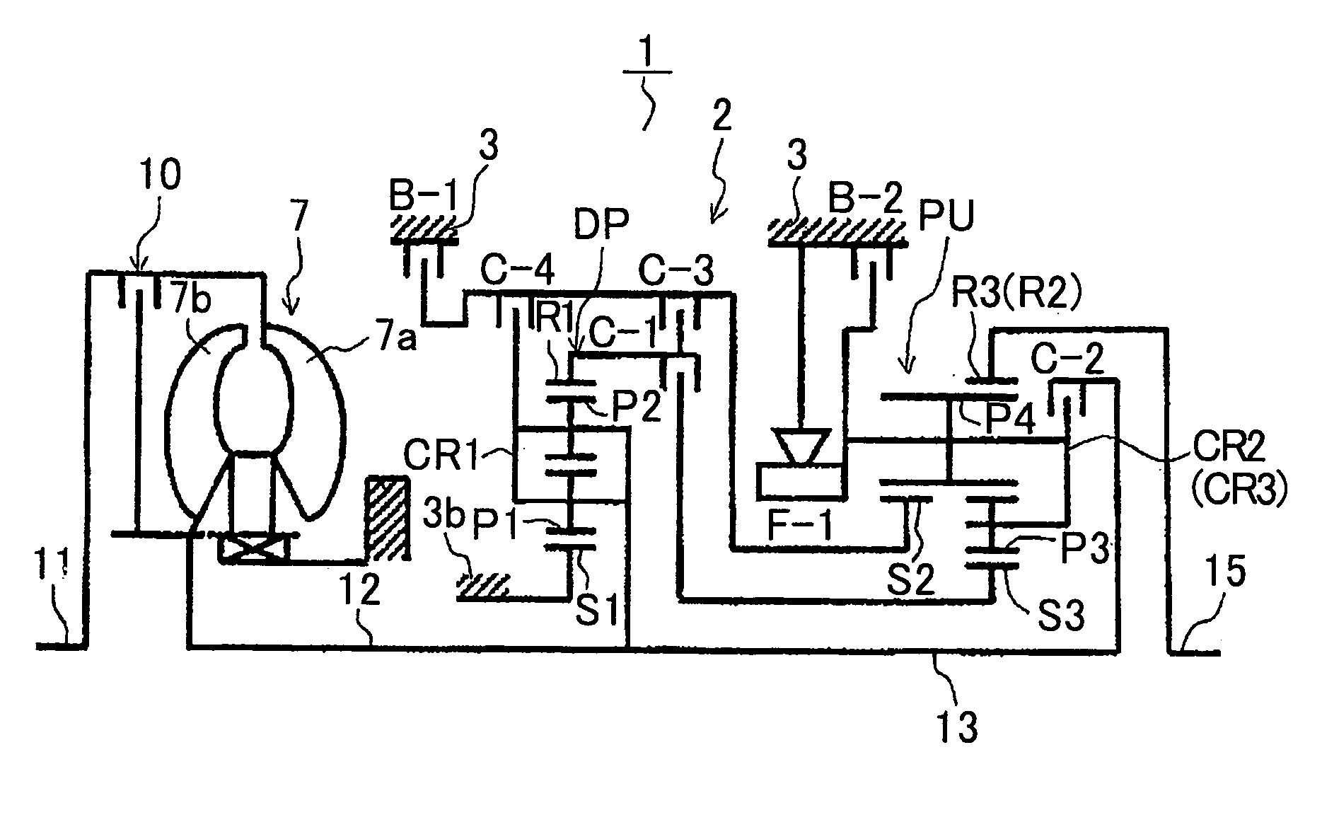
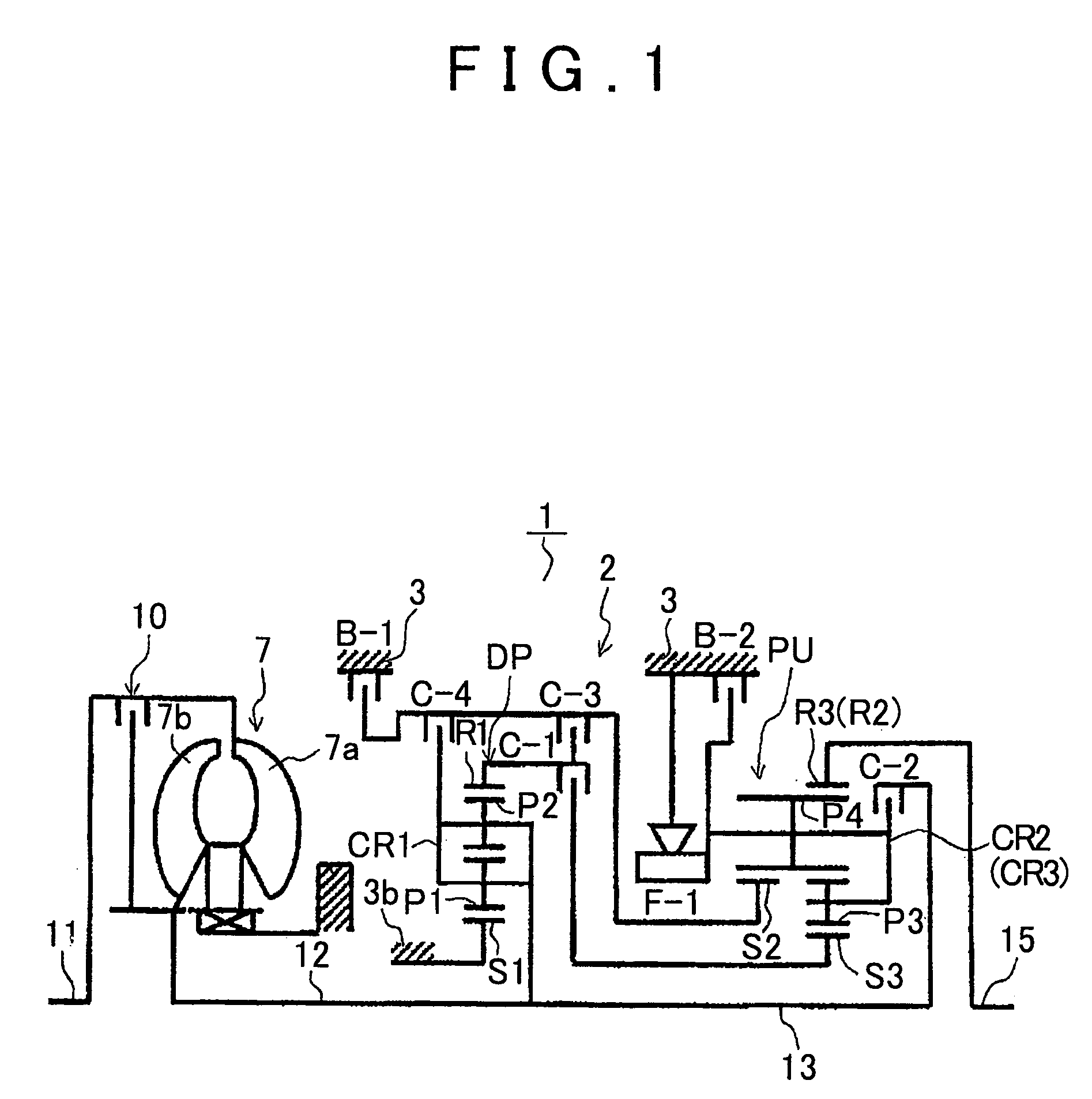
[0023] First, a schematic structure of the staged automatic transmission (below, referred to simply as an “automatic transmission”) in which an exemplary embodiment of the present invention can be applied will be explained with reference to FIG. 1. As shown in FIG. 1, a preferable automatic transmission 1 that is used, for example, in an FR type (front engine, rear drive) vehicle has an input shaft 11 for the automatic transmission 1 that is able to connect to an engine (not illustrated), and is provided with a torque converter 7 that is disposed concentrically with the input shaft 11 in the axial direction and a speed change mechanism 2.

[0024] The torque converter 7 has a pump impeller 7a that is connected to the input shaft 11 of the automatic transmission 1 and a turbine runner 7b to which the rotation of the pump impell...


PUM


Abstract

A hydraulic control apparatus, provided with a manual shift valve that outputs a forward range pressure and a reverse range pressure, and a linear solenoid valve that outputs an engagement pressure to the hydraulic servo that engages during reverse travel when energized, includes a fourth clutch relay valve that is interposed between the linear solenoid valve and the hydraulic servo. The fourth clutch relay valve communicates an engagement pressure of the linear solenoid valve to the hydraulic servo by locking in the normal position when a signal pressure of the solenoid valve is input, and communicates a reverse range pressure to the hydraulic servo by being switched to a fail position by the reverse range pressure during a failure in which the fourth clutch relay valve is de-energized. Thereby, it is possible to establish a reverse speed during a failure in which the solenoid valve is de-energized.

Description

INCORPORATION BY REFERENCE [0001] This application claims priority from Japanese Patent Application Nos. 2005-378391, 2005-378389, and 2005-378390, all filed on Dec. 28, 2005, the disclosures of which, including the specifications, drawings and abstracts, are incorporated herein by reference in their entirety. BACKGROUND OF THE INVENTION [0002] 1. Field of the Invention [0003] The present invention relates to a hydraulic control apparatus for an automatic transmission that is mounted, for example, in a vehicle, and in particular, relates to a hydraulic control apparatus for an automatic transmission that establishes a reverse speed by outputting an engagement pressure to the hydraulic servo of a friction engagement element by a solenoid valve that is energized when traveling in reverse during normal operation. [0004] 2. Description of the Related Art [0005] Conventionally, a staged automatic transmission that is mounted, for example, in a vehicle, enables establishing each shift spe...

Claims


Application Information

Patent Timeline
Patent Type & Authority Applications(United States)
IPC IPC(8): F16H61/26F16H61/12
CPCF16H61/12F16H2061/122F16H2061/1232F16H2061/126Y10S477/906Y10T477/6939Y10T477/693973Y10T477/6936Y10T477/693635
Inventor SATO, NOBUHIROYAMAGUCHI, TETSUYANODA, KAZUYUKIFUKATSU, AKIRAIWASE, MIKIONOZAKI, KAZUTOSHIHONDA, ATSUSHI
Owner AISIN AW CO LTD
Why Eureka
Try Eureka