
Method for operating a drive train of a vehicle
Patent Information
- Authority / Receiving Office
- US · United States
- Current Assignee / Owner
- Publication Date
- 2007-07-19
- Estimated Expiration
- Not applicable · inactive patent
Smart Images
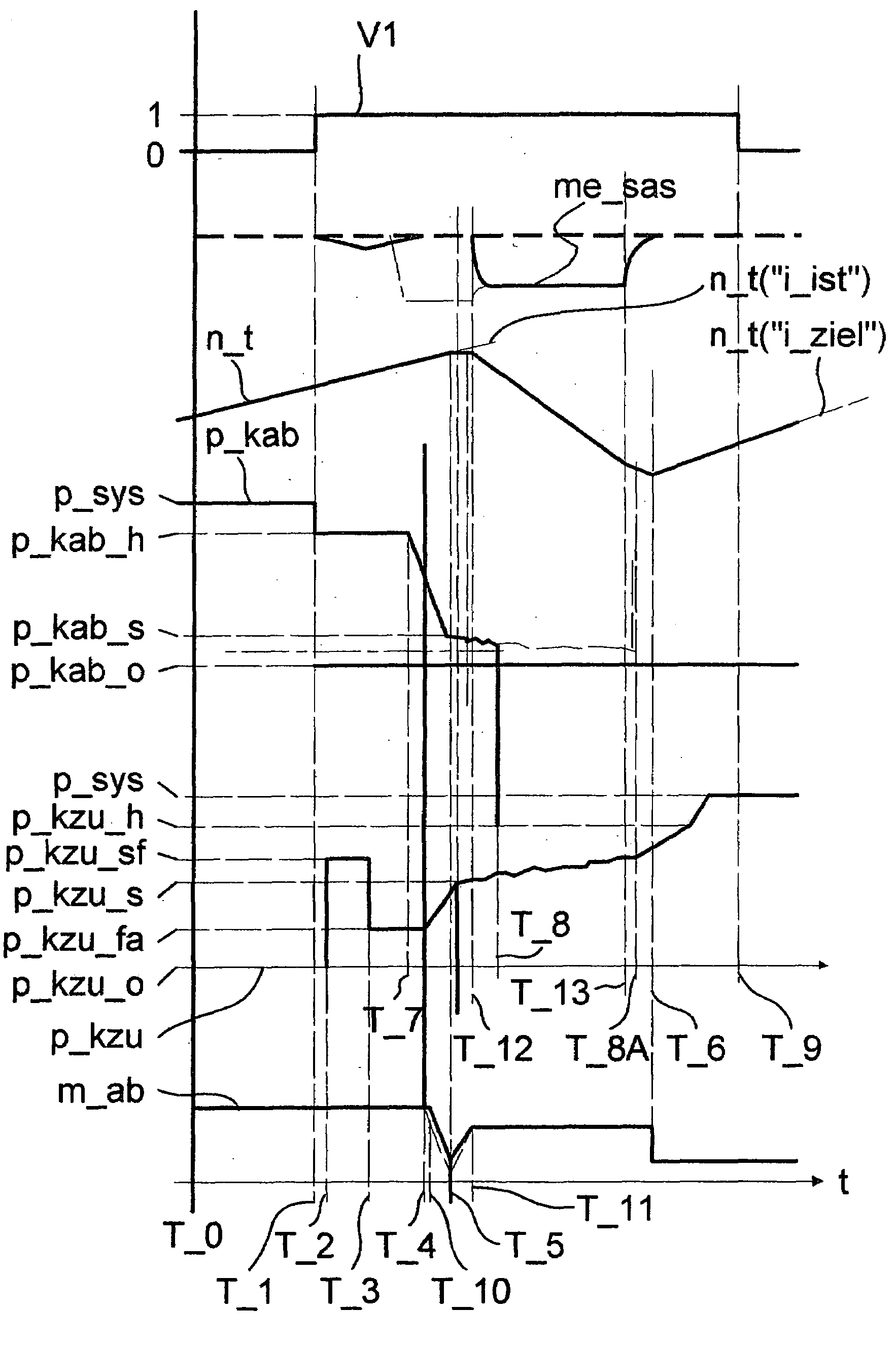
Figure 1 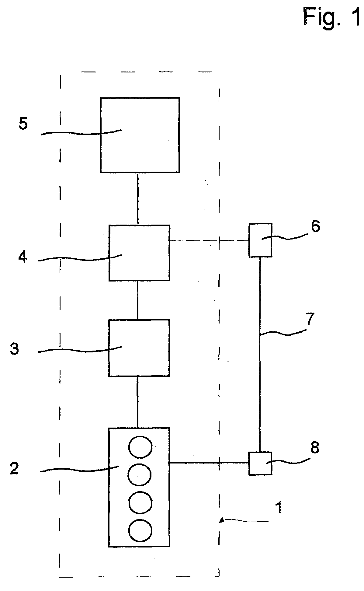
Figure 2 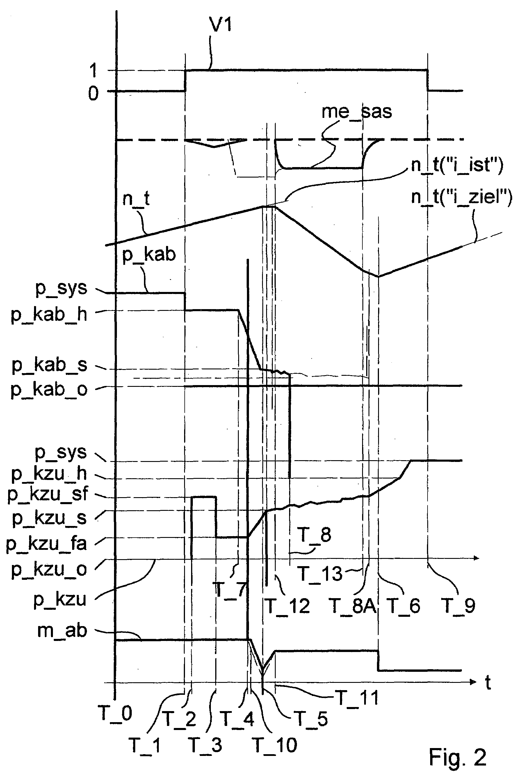
Figure 3
Abstract
Description
[0001] This application claims priority from German Application Serial No. 10 2006 002 122.3 filed Jan. 17, 2006.FIELD OF THE INVENTION
[0002] The invention concerns a method for operating a drive train of a vehicle.BACKGROUND OF THE INVENTION
[0003] In the automatic transmissions and twin-clutch transmissions known from the practice, ratio changes needed in the transmission are converted as so-called overlapping gearshifts. Here a shifting element, such as a frictionally engaged multi-disc clutch in the power flow of a drive train of a vehicle, is switched out of the flow of power by way of a variable time, pressure profile or of a variable curve of a hydraulic control pressure of the shifting element to be engaged. At the same time, a shifting element to be engaged in the flow of power of the drive train for representing the target ratio sought by the needed gearshift is engaged in the flow of power by way of a variable curve dependent on the operative state of the control pressure of ...
Examples
Embodiment Construction
[0025]FIG. 1 shows an extensively schematized representation of a drive train 1 of a motor vehicle. The drive train 1 comprises, among others, one prime mover 2, one hydrodynamic torque converter 3, having a turbine as starting element, one transmission device 4, designed as an automatic transmission for representing different ratios and one output 5.
[0026]In the traction operation of the drive train 1, an input torque of the prime mover 2 is passed to the output 5 of the vehicle, via the hydrodynamic torque convert 3 and the automatic transmission 4 in the respectively adjusted ratio in the automatic transmission 4, corresponding to transformed height. In the coasting operation of the drive train 1, a torque in the drive train 1 is passed, starting from the output 5, via the automatic transmission 4, and the hydrodynamic torque converter 3 in the direction of the prime mover 2.
[0027]In a transmission control unit 6, with reference to the operation parameters shown in FIG. 2, using ...