Method and device for supporting verification, and computer product

a verification method and computer technology, applied in the direction of cad circuit design, program control, instruments, etc., can solve the problems of large number of patterns that cannot be created manually, significant simulation results cannot be obtained, and limited patterns that can be created manually

Inactive Publication Date: 2007-07-19
FUJITSU LTD
View PDF1 Cites 9 Cited by
  • Summary
  • Abstract
  • Description
  • Claims
  • Application Information

AI Technical Summary

Benefits of technology

[0045]It is an object of the present invention to at least

Problems solved by technology

Otherwise, a significant simulation result cannot be obtained.
A large number of patterns cannot be created manually.
Therefore, ordinarily, patterns that can be created manually are limited to patterns for the request (i).
However, many procedures are required to create the pattern generator, and many errors occur.
Therefore, the request “(ii) testing as wide a range of situations as possible” cannot be met.
However, the conventional technology, such as that in “Constraint Synthesis for Environment Modeling in Functional Verification”, does not

Method used


Image

  • Method and device for supporting verification, and computer product
  • Method and device for supporting verification, and computer product
  • Method and device for supporting verification, and computer product

Examples


first embodiment

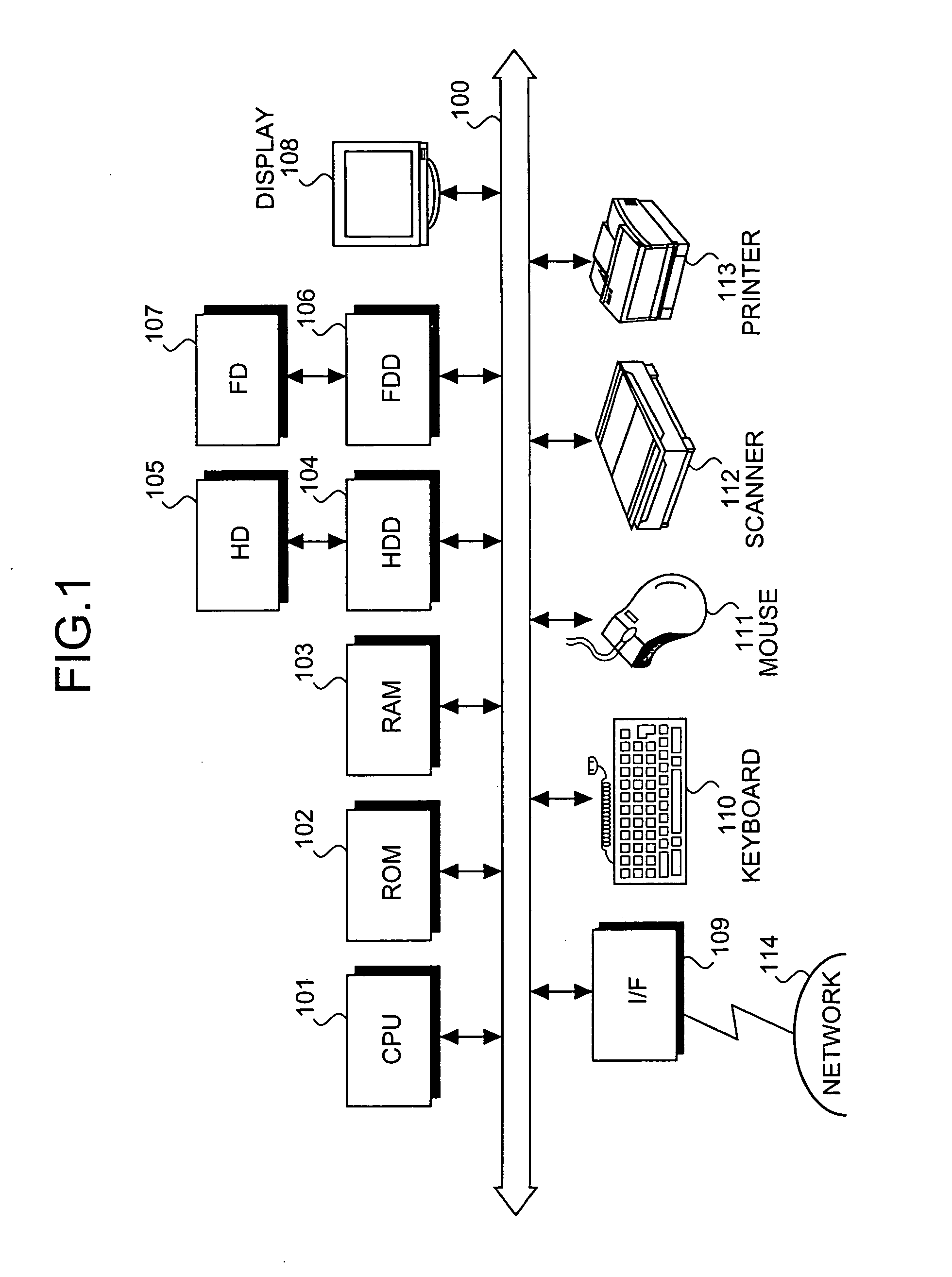
[0068]FIG. 1 is a schematic of a verification support device according to the invention. The verification support device includes a central processing unit (CPU) 101, a read-only memory (ROM) 102, a random-access memory (RAM) 103, a hard disk drive (HDD) 104, a hard disk (HD) 105, a flexible disk drive (FDD) 106, a flexible disk (FD) 107, a display 108, an interface (I / F) 109, a keyboard 110, a mouse 111, a scanner 112, and a printer 113. The FD 107 is an example of a removable recording medium. Each component is connected by a bus 100.

[0069]The CPU 101 controls the overall verification support device. The ROM 102 stores programs such as a boot program. The RAM 103 is used as a work area of the CPU 101. The HDD 104 controls reading and writing of data from and to the HD 105 under the control of the CPU 101. The HD 105 stores the data written under the control of the HDD 104.

[0070]The FDD 106 controls reading and writing of data from and to the FD 107 under the control of the CPU 101...

second embodiment

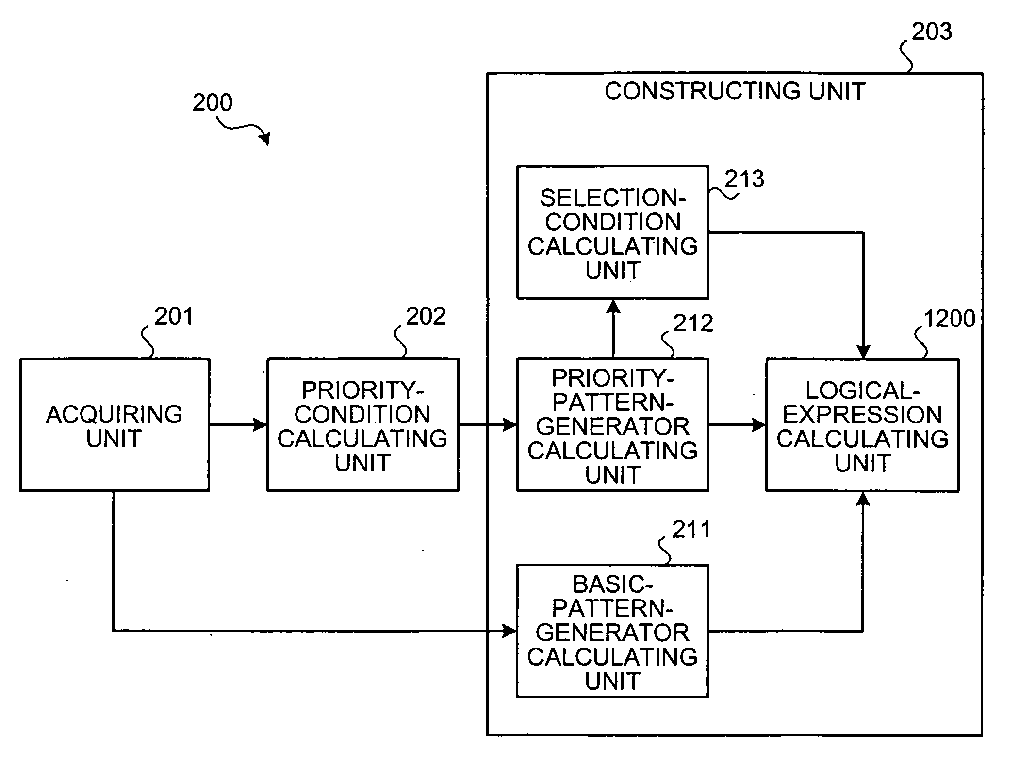
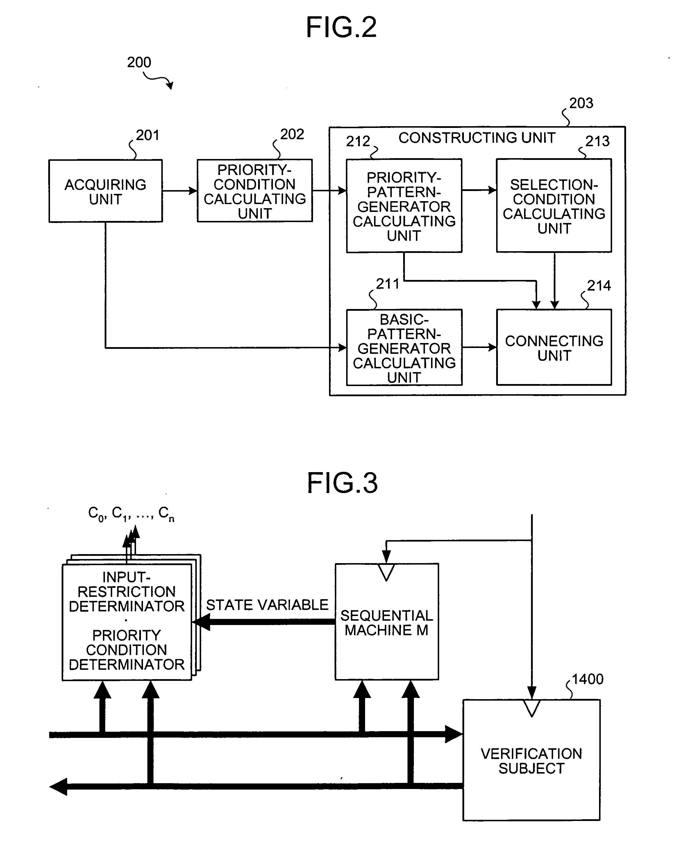
[0144]FIG. 12 is a functional block diagram of a verification support device 200 according to the A logical-expression calculating unit 1200 calculates a restriction with priority condition logical expression C, based on the logical expression C0, the logical expression Ck, and the logical expression Sk. The restriction with priority condition logical expression C satisfies the input-restriction condition (C0) and the priority condition (Ck). The logical expression C0 expresses the input-restriction condition (C0). The logical expression Ck expresses the priority condition (Ck). The logical expression Sk expresses the priority pattern selection condition (Sk). Specifically, the restriction with priority condition logical expression C is calculated using a following equation.

C=Sk·Ck+ Sk·C0  (48)

[0145]Specifically, functions of the logical-expression calculating unit 1200 are actualized by the CPU 101 executing a program recorded on, for example, the ROM 102, the RAM 103, the HD 105,...


PUM


Abstract

In a verification support device, a logical expression expressing an operation of a pattern generator can be acquired. The pattern generator includes a basic pattern generator, priority pattern generators, priority pattern selection conditions, and selector circuits. The selector circuits connect the basic pattern generator, the priority pattern generators, and the priority pattern selection conditions. Output of the basic pattern generator and outputs of the priority pattern generators are respectively connected to a signal input of a corresponding selector circuit. Outputs of the priority pattern selection conditions are connected to an ON/OFF control input of each selector circuit. An n-th selector circuit, among all selector circuits, is connected to an input terminal of a verification subject.

Description

CROSS-REFERENCE TO RELATED APPLICATIONS[0001]This application is based upon and claims the benefit of priority from the prior Japanese Patent Application No. 2006-007940, filed on Jan. 16, 2006, the entire contents of which are incorporated herein by reference.BACKGROUND OF THE INVENTION[0002]1. Field of the Invention[0003]The present invention relates to a technology for supporting hardware logic verification.[0004]2. Description of the Related Art[0005]Conventionally, a hardware module is generally configured to operate normally when an input pattern provided in a specification is received. If an input pattern that is not originally permitted is received, no operation is specified. Therefore, when a logic simulation is performed for each module, the input pattern to be input into the module should be one provided in the specification. Otherwise, a significant simulation result cannot be obtained.[0006]The input pattern can be created using a pattern manually created in advance. Th...

Claims


Application Information

Patent Timeline
IPC IPC(8): G06F17/50
CPCG01R31/31703G06F17/5022G01R31/318357G01R31/318342G06F30/33
Inventor IWASHITA, HIROAKI
Owner FUJITSU LTD
Why Eureka
Try Eureka