
Servomechanical inker for a container decorator

Inactive Publication Date: 2007-07-26
BALL CORP
View PDF18 Cites 8 Cited by
  • Summary
  • Abstract
  • Description
  • Claims
  • Application Information

AI Technical Summary

Benefits of technology

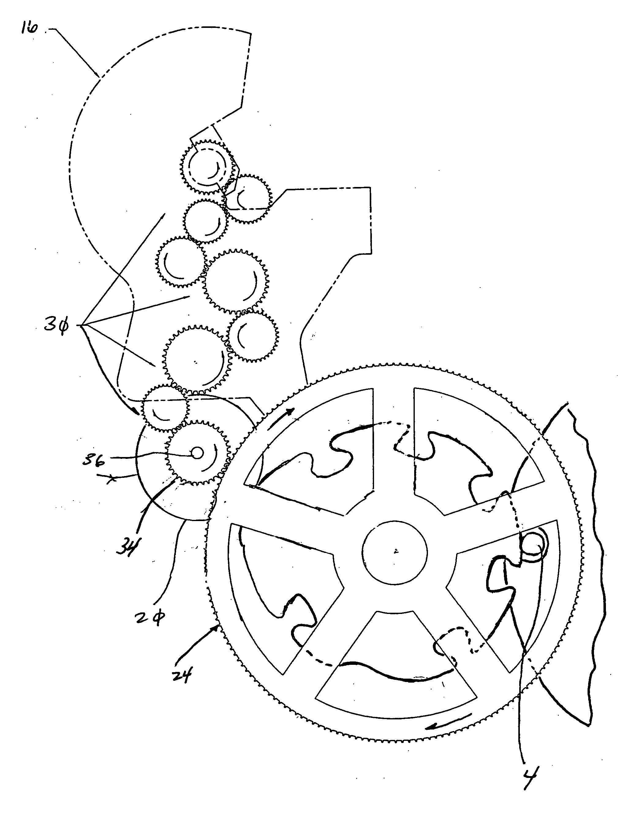
[0010] It is one aspect of the present invention to provide a container inking apparatus that applies a predetermined multi-colored design onto a container, such as a metallic beverage container. More specifically, one embodiment of the present invention increases the efficiency of prior art inking apparatus by replacing a plurality of pinion gears that are rotated by a bull gear with a plurality of servo-mechanical motors (“servo motors”). One embodiment of the present invention utilizes a servo motor associated with each inker station of the inker apparatus. The servo motor generally includes a shaft that is interconnected to a plate cylinder that includes an arcuate plate with a design depending therefrom. Each shaft rotates the plate cylinder and an ink station gear associated with the inker station. As the ink station gears rotate, a plurality of rollers inside the inker station rotate to deposit ink onto the plate cylinder. As the plate cylinder rotates, it engages a segment of a blanket cylinder that includes an elastic or rubber blanket designed to deposit an inked pattern on the blanket. As the blanket cylinder rotates, the inked pattern progresses to an adjacent inker station to receive another inked design. This process is repeated until the inked portion of the blanket interacts with all of the colors and designs that are to be placed on the container. Once the blanket portion is completely inked, it is rotatably positioned adjacent to a container that is interconnected to a mandrel positioned on a spindle disc rotating in an opposite direction of the blanket cylinder. As the blanket cylinder engages the container, the container rotates due to the frictional force imparted by the blanket thereby facilitating deposition of the inked design onto the outer surface of the container. Although these types of inkers are generally used to apply a design to a metallic container, the invention described herein is applicable for applying ink or other medium to any type of container or surface, and is not limited to metallic surfaces.
[0011] As briefly mentioned above, each shaft that is rotated by each servo motor is interconnected to an inker shaft gear that is in operable engagement with a plurality of gears that are situated inside the inker station. Each inker station also includes a reservoir containing ink of a predetermined color. As the gears of the inker station rotate, they rotate the plurality of rollers that transfer ink from the reservoir onto the plate cylinder. Since the bull gear is designed to rotate the plurality of pinion gears that rotate the plate cylinder and the inker shaft gears, it is advantageous to provide a system that allows for more accurate timing of the individual component rotations, thereby helping to ensure that the proper design is placed on the blanket. Thus, one embodiment of the present invention allows for the servo motors to be selectively adjusted, or “tuned”, to ensure that the ink emanating from the inker station is placed on the plate cylinder at the correct location and that the rotation of the plate cylinder is such that the design carried by the plate cylinder is placed on the blanket at the proper location.
[0012] It is still yet another aspect of the present invention to provide an inker station that reduces the amount of time to replace the plates, also referred to in the art as “labels”, that are interconnected to the plate cylinders. More specifically, each prior art apparatus require an individual to remove the pinion gears in order to remove each plate cylinder shaft along with each plate cylinder to replace the plates. Once the plate changes were finished, the heavy pinion gears would have to be operably engaged to the bull gear, thus increasing the risk of injury to maintenance personnel, for example, from pinching their fingers between the gear teeth of the pinion gear and the bull gear. Thus, one embodiment of the present invention omits the pinion gears and includes a coupler that interconnects the servo motors directly to the shafts, thereby allowing the servo motors to be disconnected from the shaft to facilitate maintenance activities. In addition, once the new plates are placed on the plate cylinders, the servo motors allow for selective adjustments to help ensure that the timing of the system is such that the inked plates contact the blanket at the correct location. This aspect of the invention also reduces down time wherein the production facility thereby increases efficiency.

Problems solved by technology

Once the plate changes were finished, the heavy pinion gears would have to be operably engaged to the bull gear, thus increasing the risk of injury to maintenance personnel, for example, from pinching their fingers between the gear teeth of the pinion gear and the bull gear.
Incorrect meshing of the pinion gear to the bull gear may cause the inker shaft gear to unevenly load the gears of the inker station in such a way to increase friction between the rollers.
This friction generates heat between the rollers that may have adverse affects on the rubber rollers themselves, and that may cause ink degradation.

Method used


Image

  • Servomechanical inker for a container decorator
  • Servomechanical inker for a container decorator
  • Servomechanical inker for a container decorator

Examples


Embodiment Construction

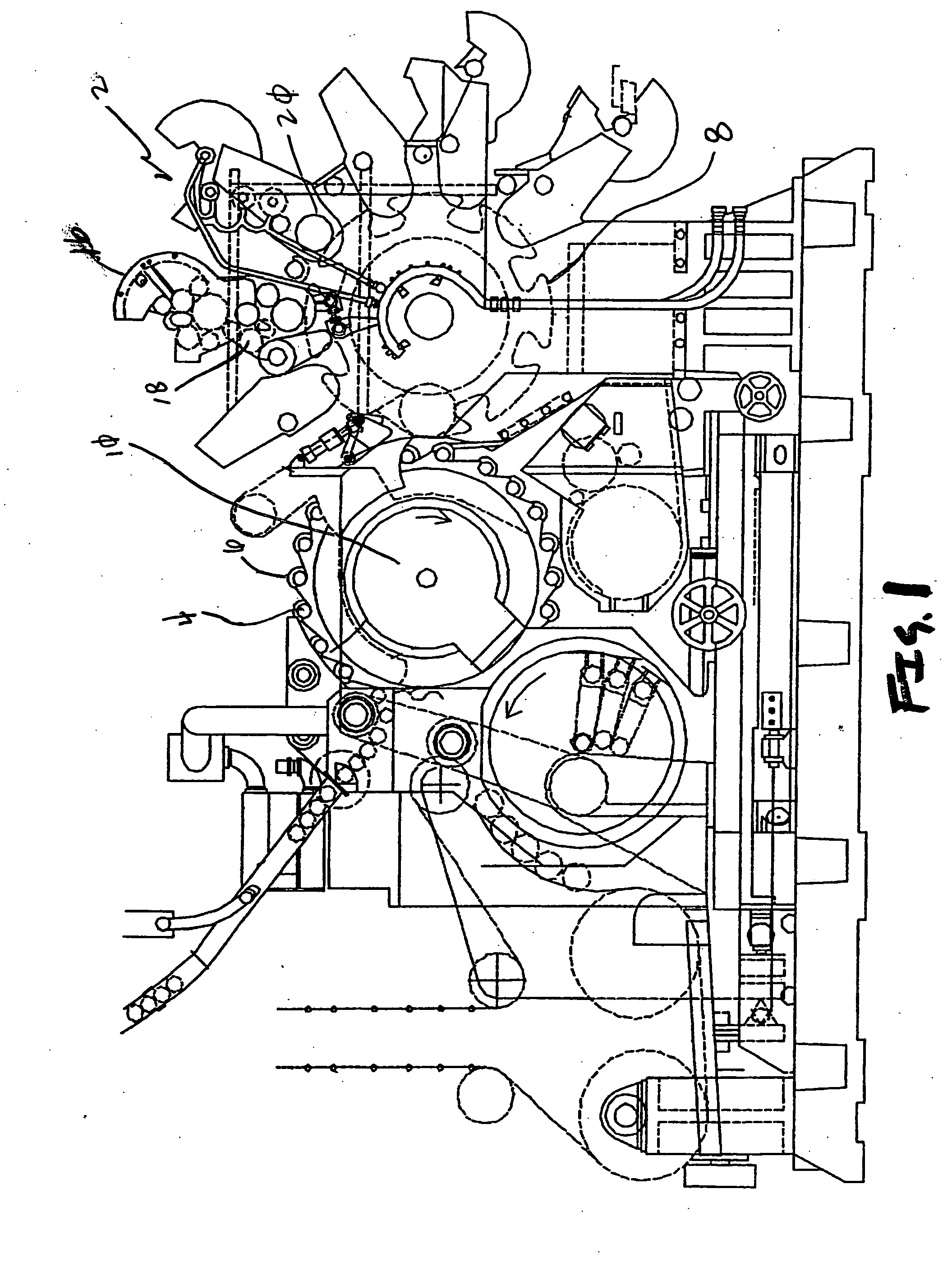
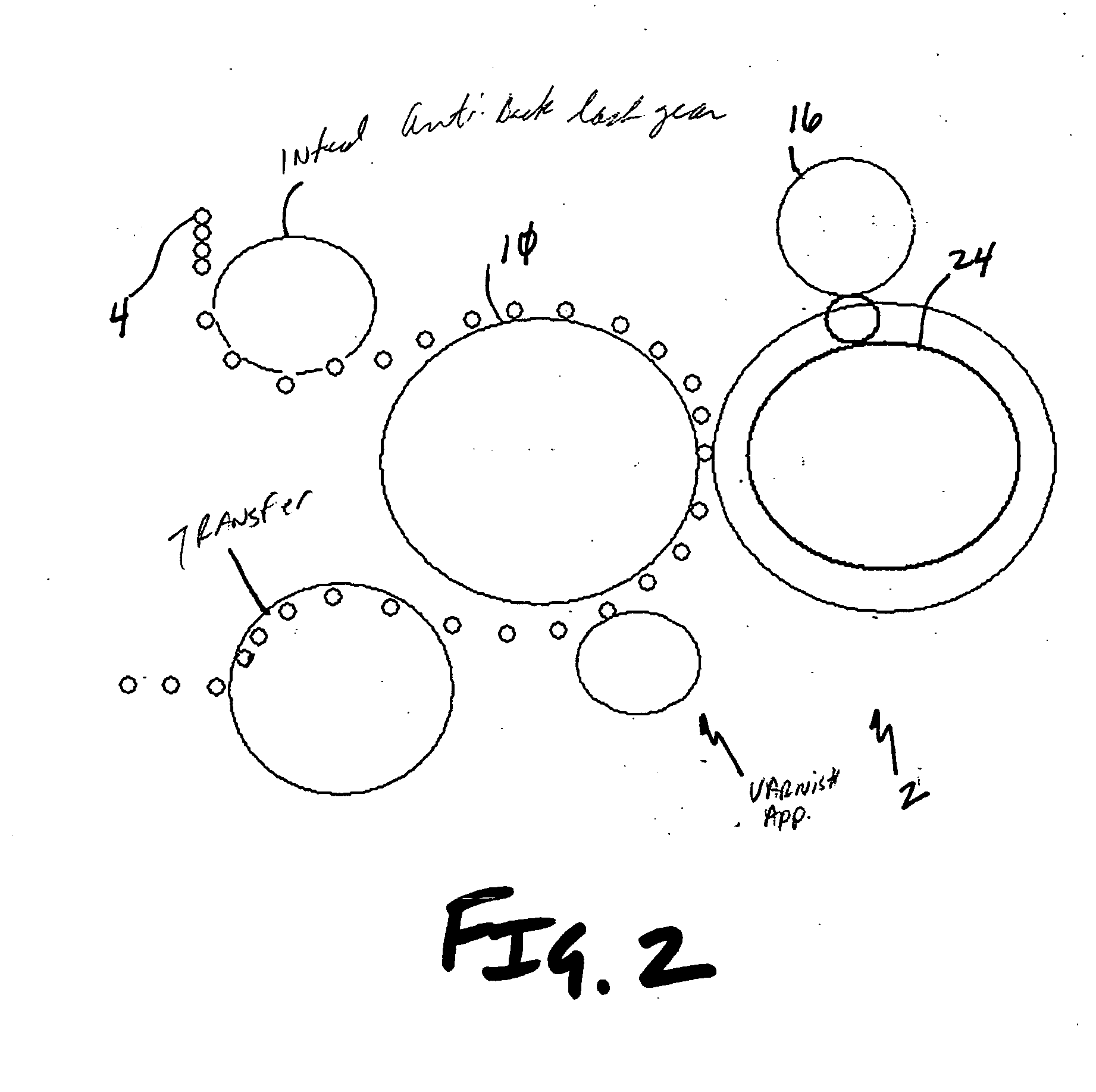
[0043] Referring now to FIGS. 1-17, an inker apparatus 2 is shown that applies various colors of ink onto a container 4. More specifically, inker apparatus 2 are well known in the art wherein a plurality of containers 4 are fed onto a rotating mandrel 6. A blanket cylinder 8 is also included that rotates parallel to, and in conjunction with, a spindle disc 10 that secures the mandrel 6. A blanket 12 wrapped around the blanket cylinder 8 is selectively coated with ink from a plurality of individual inker stations 16. The ink from the inker stations 16 is applied via rollers 18 onto a plate cylinder 20 that secures a plate 22 with a raised design. Once the various colors of ink are individually applied onto their corresponding plates 22, the ink from each plate is deposited on a segment of the blanket 12. When the inked blanket 12 is placed adjacent to the container 4, which is situated on the mandrel 6 of the spindle disc 10, the oppositely rotating members will rotate the container ...


PUM


Abstract

An improved inking apparatus is provided that omits the use of the bull gear generally known in the art. More specifically, bull gears have traditionally been used in inking apparatus to rotate pinion gears that rotate shafts interconnected to plate cylinders. Plate cylinders in turn apply ink to a blanket that ultimately applies indicia to a container such as a beverage can. The rotating shaft also communicates with a plurality of gears that operate the inking stations that transfer the ink onto the plate cylinder. One embodiment of the present invention omits the bull gear and the pinion gears and provides an electro-mechanical driver that rotates the shafts to allow a controller to monitor and individually control the timing of plate cylinder rotation and inker station gear rotation thereby increasing efficiency and maintenance personnel safety.

Description

FIELD OF THE INVENTION [0001] The present invention relates to apparatus for applying ink and indicia to a container. More specifically, one embodiment of the present invention includes a plurality of servo-mechanical motors that rotate shafts interconnected to plate cylinders that transfers ink and indicia to a blanket that applies the inked pattern onto a container. BACKGROUND OF THE INVENTION [0002] Automated container decorating apparatus are generally employed to apply indicia, such as artwork, designs, trademarks, etc. onto a container, such as a metallic beverage can. An apparatus indicative of the state of the art is disclosed in U.S. Pat. No. 6,651,552 to Didonato (“Didonato”), which is incorporated by reference in its entirety herein. The Didonato apparatus includes an infeed that directs containers onto a spindle disc that includes a plurality of mandrels depending therefrom that receive the containers and allows them to rotate relative to the spindle disc. A print sectio...

Claims


Application Information

Patent Timeline
IPC IPC(8): B41F5/00
CPCB41F17/002B41F31/004B41F17/22
Inventor CONRAD, EARL P.
Owner BALL CORP
Learn More