Reading Card

a reading card and card base technology, applied in the field of cards, can solve the problems of poor optics in terms of the resolution provided by fresnel lenses, creating blurring or distortion of text, and generally not providing suitable viewing enhancement for reading purposes, etc., to achieve the effect of improving the thickness over the card base, strengthening the bonding force, and improving the quality of the card bas

Inactive Publication Date: 2007-07-26
WATERS
View PDF3 Cites 14 Cited by
  • Summary
  • Abstract
  • Description
  • Claims
  • Application Information

AI Technical Summary

Benefits of technology

[0010] In a preferred form, the lens portion and card base are molded at the same time so that the integral reading lens portion is thicker than the remaining thin portion of the card base. That is, the reading lens has at least some portion of its light refractive surfaces that extend beyond the corresponding main surfaces of the card base. Due to the increased thickness over the card base, a robust construction is provided in the area most in need of strength enhancement, i.e., the lens, with such relatively thin reading cards. In addition, the integral lens and card body can be formed of a hard and durable molded plastic material, e.g., acrylic polycarbonate, which is not a suitable material for stamped Fresnel lenses. This material provides the thin card body with a robust construction. Accordingly, the preferred reading card including the integral reading lens thereof is contrasted with stamped Fresnel lenses which can be completely recessed from or at least

Problems solved by technology

As discussed in applicant's U.S. Pat. No. 6,390,372, which is incorporated by reference as if reproduced in its entirety herein, Fresnel lenses generally do not provide suitable viewing enhancement for reading purposes as the primary focus is magnification rather than vision correction.
In this regard, Fresnel lenses generally have poor optics in terms of the resolution they provide creating blurring or distortion of the text to be read.
Also, Fresnel lenses typically do not have a well-defined diopter rating which can vary sometime in the range of between four and six, which generally is more magnification than is necessary for reading lenses.
Another drawback is that manufacture of Fresnel lenses usually requires a soft plastic material such as PVC for being pressed to form the concentric stepped grooves and ridges of these lenses.
This softer lens material is not desirable for lenses incorporated into thin cards as they are likely to be damaged due to the handli

Method used


Image

  • Reading Card
  • Reading Card
  • Reading Card

Examples


Embodiment Construction

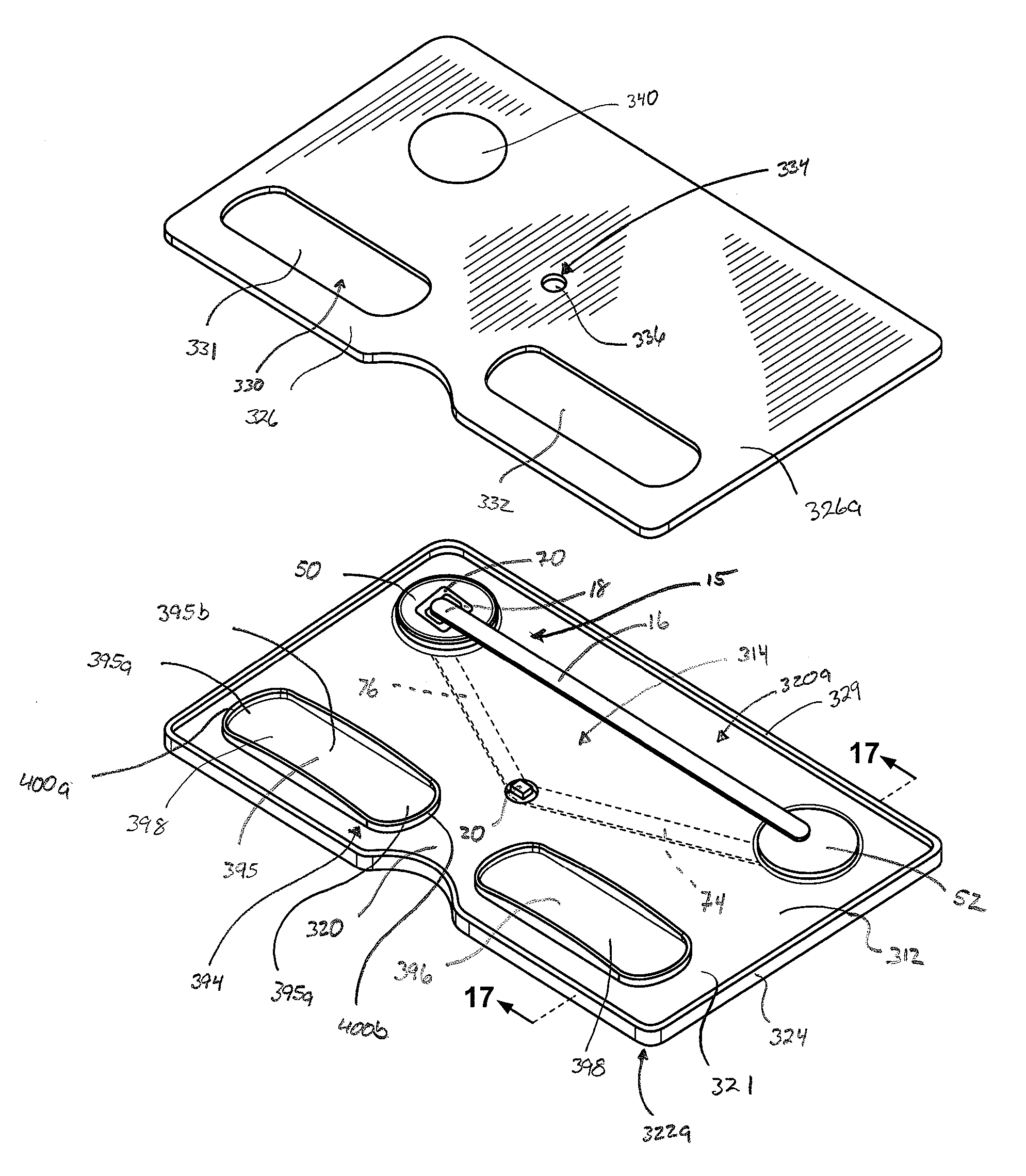
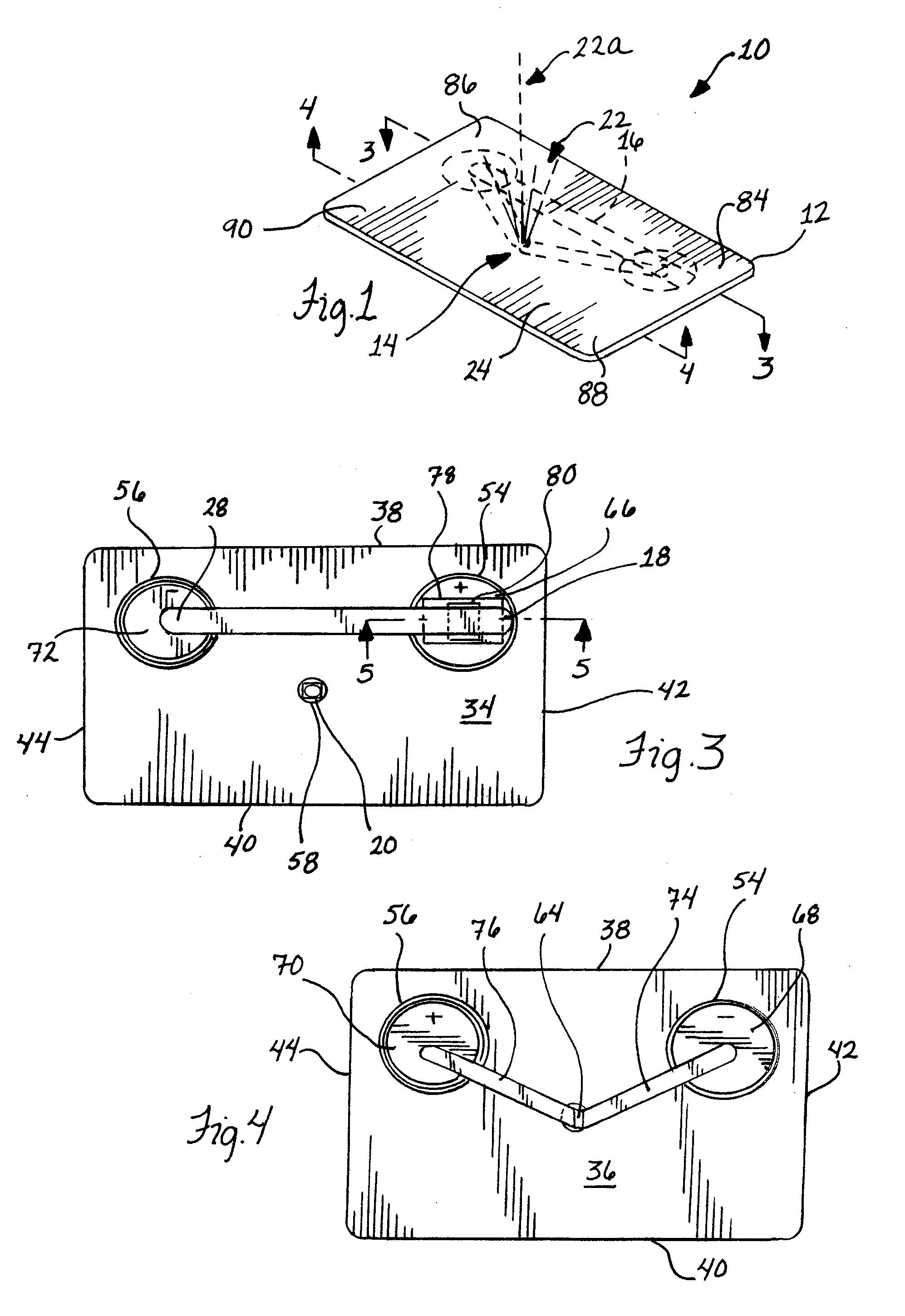
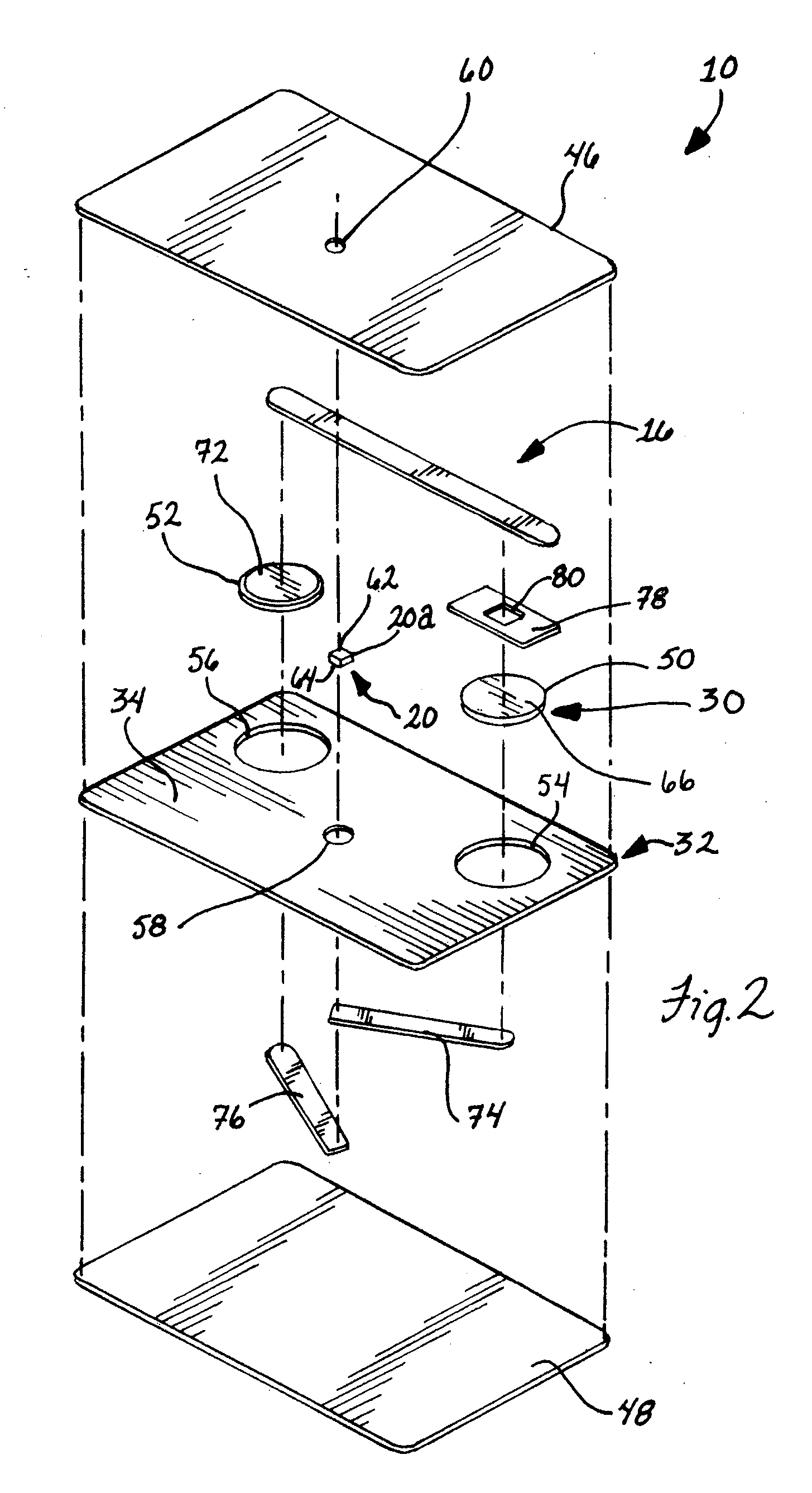
[0033] In FIGS. 1 and 2, a light card 10 is shown including a card member 12 that carries a light source 14 and a switch bar 16 that is operable to energize the light source 14. It is preferred that the switch bar 16 be independent or distinct from the light source 14 so that its operation to perform the switching function thereof does not mechanically affect the components of the light source 14 and thus is solely operable to provide power to or remove power from the light source 14. In addition, the switch bar 16 can be arranged and configured so that it is easy to engage and push the switch bar 16 and in particular end 18 thereof for flexing the bar 16 to energize the light source 14. In this regard, it is preferred that the switch bar 16 have an elongate and thin, flat strip configuration and be of a resilient, conductive metallic material. In this manner, the switch bar or strip 16 is designed to be robust and withstand flexing thereof over thousands switching cycles without ad...


PUM


Abstract

A reading card is provided having a reading lens portion that is integrally molded in a unitary form with a card base. The lens portion is formed so as to have a well-defined diopter rating. Preferably, the lens portion includes convexly curved, continuously smooth, opposite light refractive surfaces. Generally, the lens portion can be thicker than a thin, generally flat remaining portion of the card base. The reading card can be implemented in a credit or debit card size, or used as a key ring holder. Optionally, the reading card includes a light source.

Description

CROSS-REFERENCE To RELATED APPLICATIONS [0001] This application is a continuation-in-part of prior application Ser. No. 11 / 327,573, filed Jan. 6, 2006, which is a continuation of prior application Ser. No. 10 / 946,592, filed Sep. 21, 2004, now U.S. Pat. No. 7,036,740 B2, which are both hereby incorporated by reference as if reproduced in their entirety herein.FIELD OF THE INVENTION [0002] The invention relates to cards and, more particularly, to cards that provide a viewing enhancement function. BACKGROUND OF THE INVENTION [0003] Providing thin card members having a reading lens associated with a card body such as taught in applicant's U.S. Pat. No. 6,390,372 B1 advantageously provides a compact and low profile device that allows for enhanced viewing through the lens. Such devices may be carried in a wallet or purse similar to a traditional credit card and removed when needed. These reading cards, therefore, require little storage space when not needed as opposed to the much larger s...

Claims


Application Information

Patent Timeline
IPC IPC(8): G06K19/00G06K19/06
CPCG02B27/028G02B25/008
Inventor WATERS, MICHAEL
Owner WATERS
Why Eureka
Try Eureka