
Energy-efficient electro-thermal ice-protection system

Inactive Publication Date: 2007-07-26
COX MODELS
View PDF10 Cites 46 Cited by
  • Summary
  • Abstract
  • Description
  • Claims
  • Application Information

AI Technical Summary

Benefits of technology

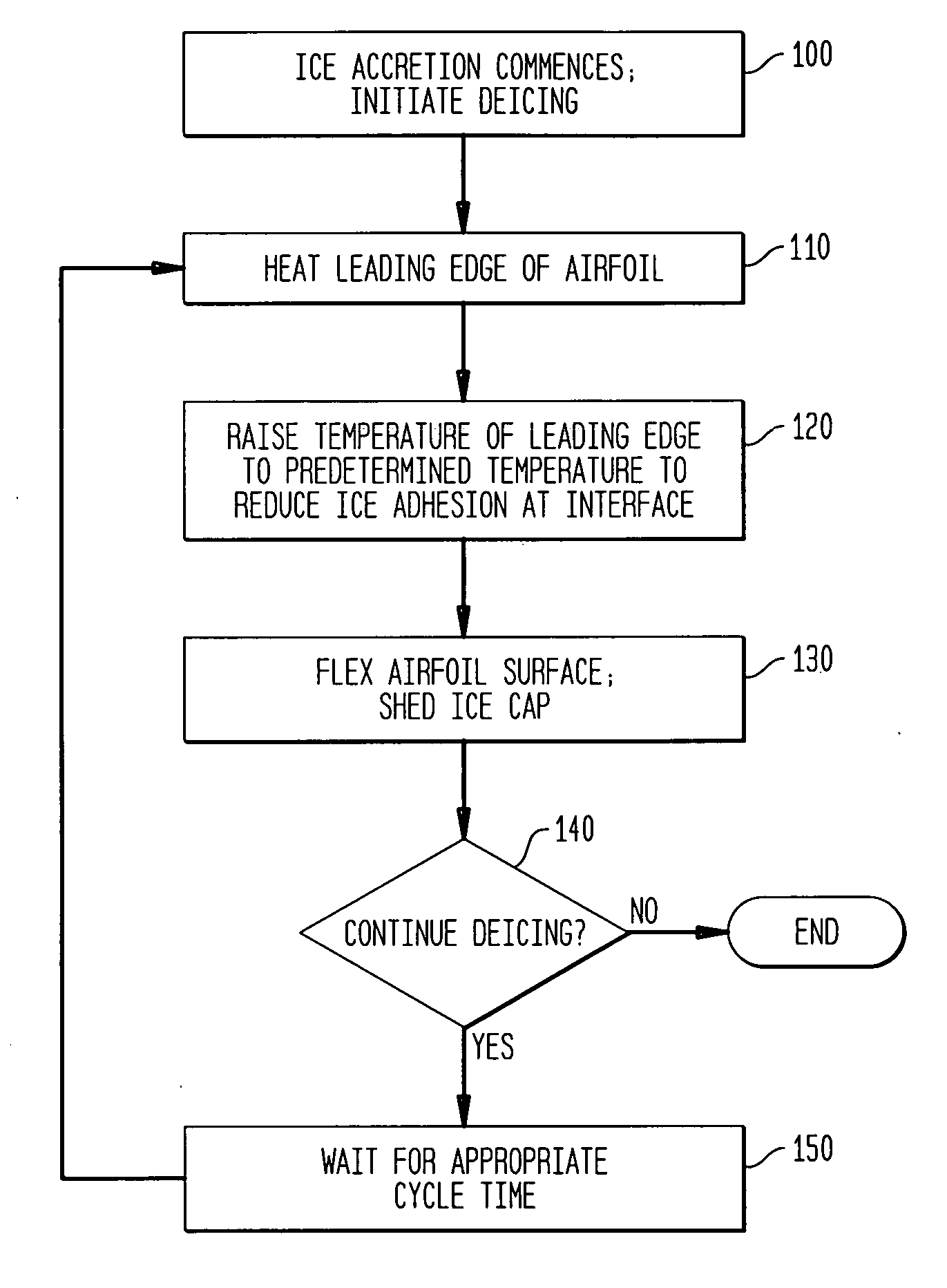
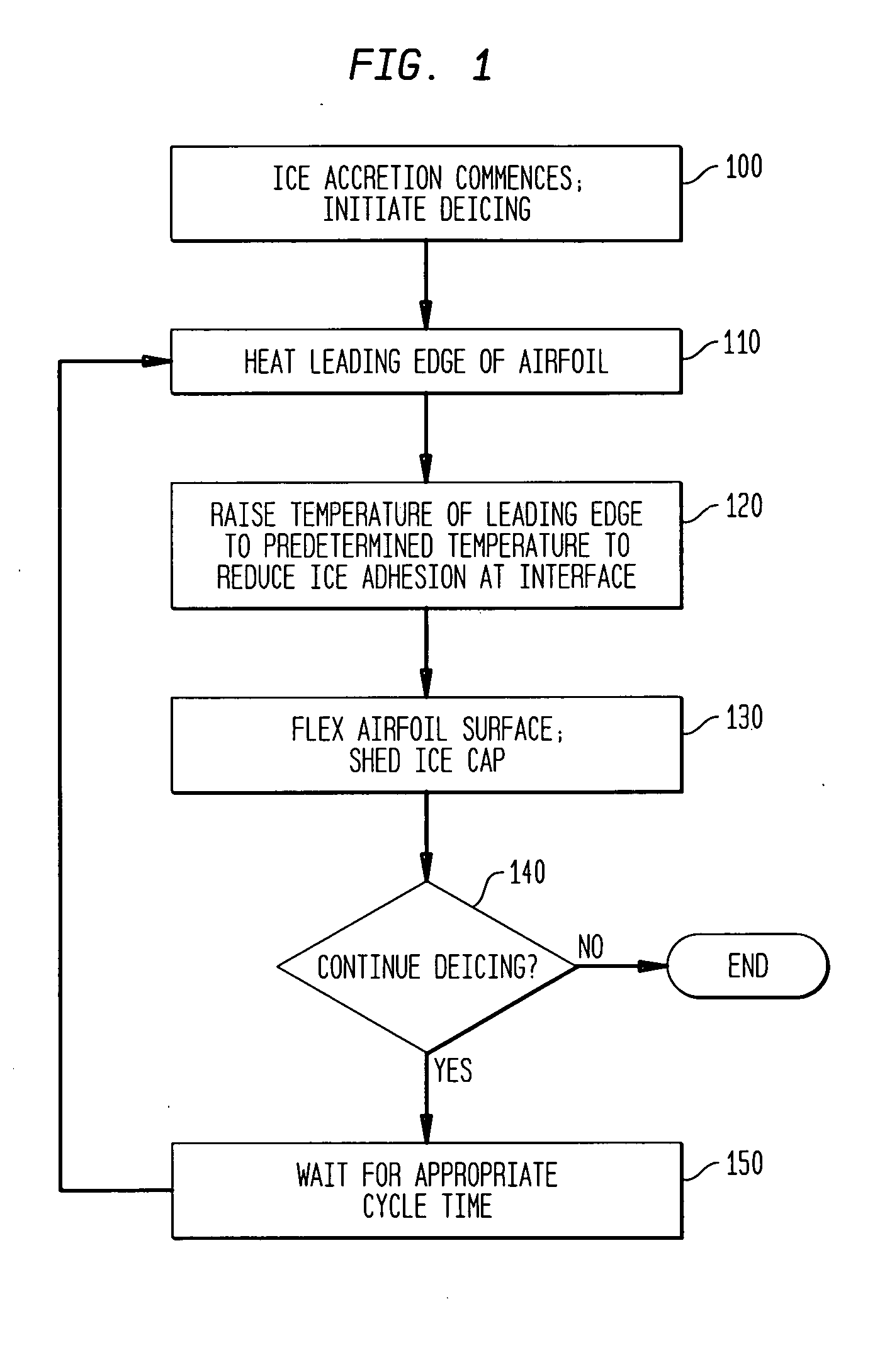
[0009] Advantageously although not necessarily, and in the preferred embodiment, energy consumption of the system is further reduced by removing accreted ice from the airfoil on a zone-by-zone basis. This is accomplished by dividing the airfoil into a series of zones that extend along the span of the airfoil and then applying heat to individual zones sequentially, one at a time. This avoids the power drain that would be required to heat the entire airfoil at once. In particular, it is possible to eliminate the continuously heated parting strip along the entire span of a typical electro-thermal de-icing system.
[0010] In the preferred embodiment, heating continues until a very thin layer of ice at the ice / skin interface is melted immediately adjacent the skin. This insures that the accreted ice is completely shed when the skin is deformed. However, this is only preferred, and it may be possible to obtain acceptable performance even if the ice is not entirely melted at the surface of the skin.
[0012] In the preferred embodiment, heating is electro-thermal. However, this is only preferred, and it may be possible to obtain acceptable performance using bleed air as a source of heat.

Problems solved by technology

Ice contamination of lifting surfaces (e.g. wings and horizontal tails) is always disadvantageous because it interferes with airflow over the surface.
This in turn increases drag, reduces lift, and reduces the angle of attack at which the airfoil enters a stall.
For example, certain lifting surfaces may use airfoils that are more or less tolerant to the effects of ice contamination than are other airfoils; a quantity of accreted ice that might only imperceptibly degrade the performance of one type of airfoil section might be a severe hazard to another type of airfoil when operated at similar or different flight conditions.
On some airplanes, there may be sufficient electrical power to operate an ice protection system that relies on electrically-generated heat (e.g., an electro-thermal deicing or anti-icing system) while on others, the available electrical power is insufficient for such a system.
For example, on an airplane having ample electrical power or bleed air, an energy intensive evaporative anti-icing system may be employed, while for a power-limited application a deicing system may be used to shed ice only when the ice accumulation reaches a predetermined distributed thickness that has been shown to degrade the performance of the airfoil to an unacceptable extent.
Although many different types of ice protection systems are available to address a wide variety of applications for ice protection, one application category is particularly problematic.
This is when the airfoil is very sensitive to ice contamination and there is limited power available for operation of an ice protection system that meets the required performance.
Furthermore, the absence of heating between deicing cycles causes the temperature of the skin to drop below freezing before runback refreeze can be created.
This applies the maximum heat and the maximum mechanical force to the accreted ice in the location where ice will most seriously degrade aerodynamic performance.

Method used


Image

  • Energy-efficient electro-thermal ice-protection system
  • Energy-efficient electro-thermal ice-protection system
  • Energy-efficient electro-thermal ice-protection system

Examples


Embodiment Construction

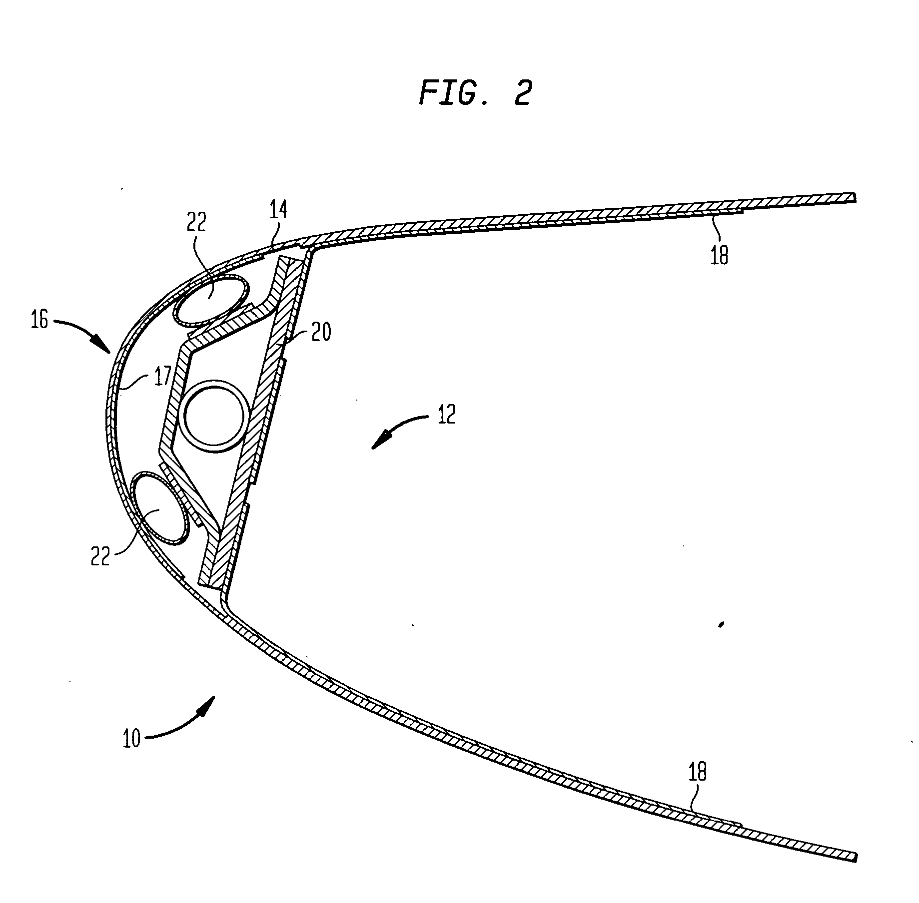
[0018] The same element is always indicated by the same reference numeral in all views. The drawings are not necessarily to scale, and parts may be enlarged for clarity.

[0019] In the following description, the ice-protected component is specifically illustrated to be an aircraft wing. This is because the present invention was designed for this application. However, the invention is not limited to use on aircraft wings and can be used on other surfaces such as horizontal stabilizers, vertical fins, aircraft inlets, and other airfoils.

[0020] The following description also assumes that icing wind tunnel tests have been or will be carried out on a model that simulates, under designed-for conditions of flight, the accretion of ice on the component to be protected. Such tests are routinely conducted during the design of an aeronautical ice-protection system, because empirical data is necessary to verify that the system performs as required within the entire performance envelope of the a...


PUM


Abstract

A region of an airfoil to be protected from accreted ice is heated to reduce the strength of the bond between the ice and the airfoil, and is mechanically deformed to shed the accreted ice after the bond has been sufficiently weakened. Heating ceases before substantial water runback is generated. The mechanical deformation and the cessation of heating occur approximately simultaneously.

Description

BACKGROUND OF THE INVENTION [0001] The invention relates to ice protection, and more particularly relates to ice protection systems for use on aircraft. In its most immediate sense, the invention relates to aircraft ice protection systems of the type in which a semi-rigid skin forms a lifting surface of the wing and in which ice is removed by flexing the skin. [0002] Ice contamination of lifting surfaces (e.g. wings and horizontal tails) is always disadvantageous because it interferes with airflow over the surface. This in turn increases drag, reduces lift, and reduces the angle of attack at which the airfoil enters a stall. For this reason, airplanes are provided with systems that protect lifting surfaces from excessive levels of ice contamination on critical regions of the lifting surface. [0003] Ice protection systems vary widely in performance. This is because different types of aircraft lifting surfaces have different sensitivities to ice contamination and, consequently, differ...

Claims


Application Information

Patent Timeline
IPC IPC(8): B64D15/16
CPCB64D15/22B64D15/12
Inventor AL-KHALIL, KAMEL
Owner COX MODELS
Learn More