

Temporary fence
- Summary
- Abstract
- Description
- Claims
- Application Information
AI Technical Summary
Benefits of technology
Problems solved by technology
Method used
Image

Examples
Embodiment Construction
[0031] The present invention will now be described by way of example and with reference to the accompanying drawings.
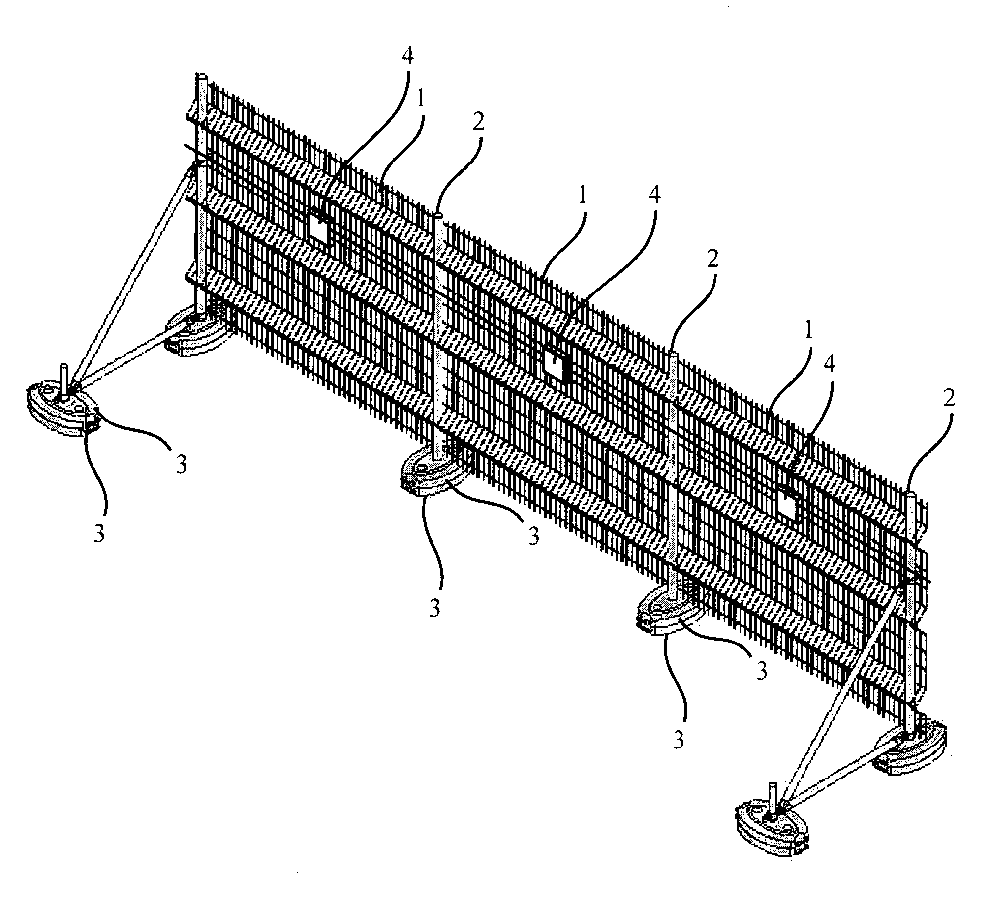
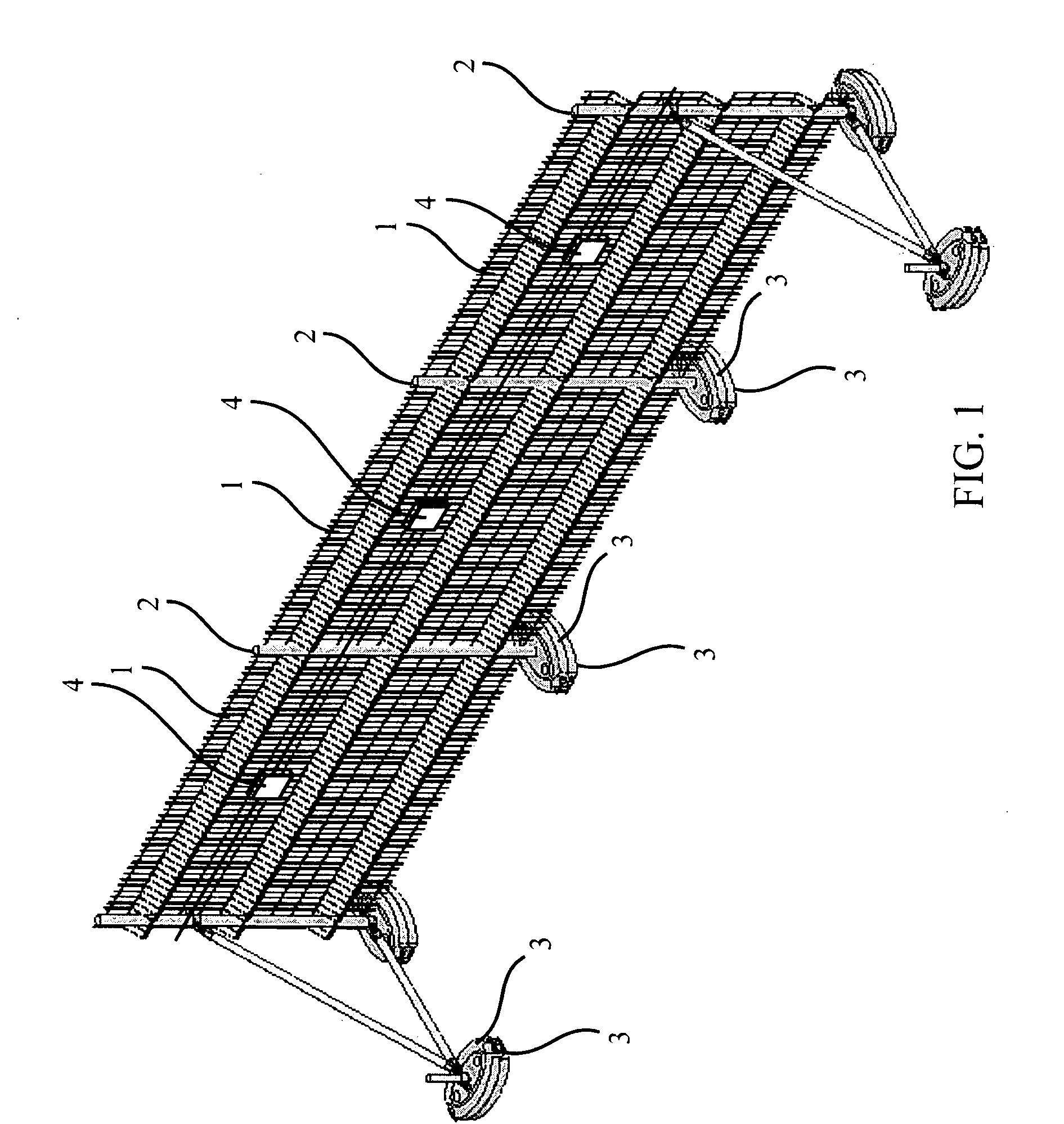
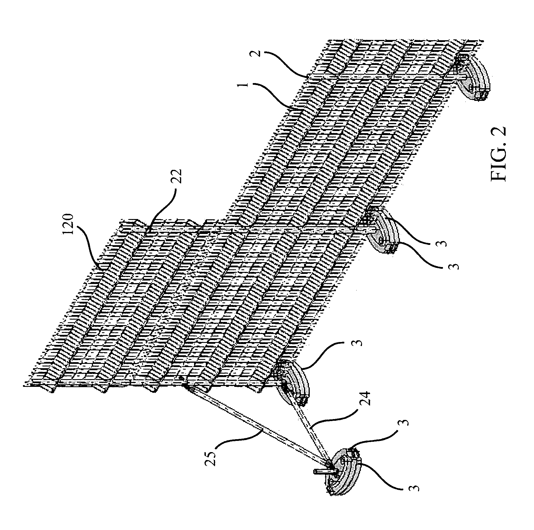
[0032]FIG. 1 illustrates a temporary fence which has a relatively simple structure, is easy to install and yet provides good protection. In one embodiment, the fence includes a plurality of fence segments 1, preferably made of welded mesh wire, of a size of about 2 meter high by 3 meter wide. The poles 2 support the two sides of each fence segment 1 and connect the fence segments into one contiguous fence.
[0033] Each pole 2 is preferably mounted on one or more elliptical bases 3. The elliptical base may help secure the fence, so that it will be more difficult to move it. The bases 3 may be laid on the ground.
[0034] The novel shape of the base 3 (elliptical rather than circular) allows to achieve improved stability in the direction that counts (along the long axis of the ellipse).
[0035] In a preferred embodiment, vibration sensors 4 are placed, such as one sensor o...
PUM
 Abstract
Description
Claims
Application Information