
Vehicle control unit and vehicle control method

Inactive Publication Date: 2007-07-26
FUJITSU GENERAL LTD
View PDF22 Cites 30 Cited by
  • Summary
  • Abstract
  • Description
  • Claims
  • Application Information

AI Technical Summary

Benefits of technology

[0009]It is therefore an object of the invention to provide a system and method of controlling a vehicle which can reduce the occurrence of feed limitation on the accessories.
[0026]With the above configurations, the available current value which the battery can supply to the electric equipments is accurately calculated. Since the economical running is performed based on the available current value and a feed limitation to the electric equipments from the battery is performed based on the total value of the necessary current values and the available current value, an unreasonable feed limitation of the electric equipment other than the safety system units can be reduced, thereby making it possible to enhance the conveniences of the user.

Problems solved by technology

Therefore, the feed limitation on the accessories other than the safety system units easily occurs at all times depending on the condition of the battery when the vehicle is restored to the normal state from the economical running state.
Here, when a feed limitation on the accessories is implemented due to the current value supplied to the electric equipments becoming insufficient, since the available current value that can be supplied to the electric equipments from the battery cannot be calculated accurately, the current value that can be so supplied is estimated lower.
Therefore, the feed limitation on the accessories is implemented more than actually necessary.
By such a feed limitation, the feed on the accessory on which the feed limitation did not actually have to be performed may be limited.
Then, there is a problem that a reproduction of musing was stopped while the user was listening thereto, the conveniences of the user being thereby damaged.

Method used


Image

  • Vehicle control unit and vehicle control method
  • Vehicle control unit and vehicle control method
  • Vehicle control unit and vehicle control method

Examples


Embodiment Construction

[0042]Hereinafter, an embodiment of the invention will be described in detail with reference to the accompanying drawings.

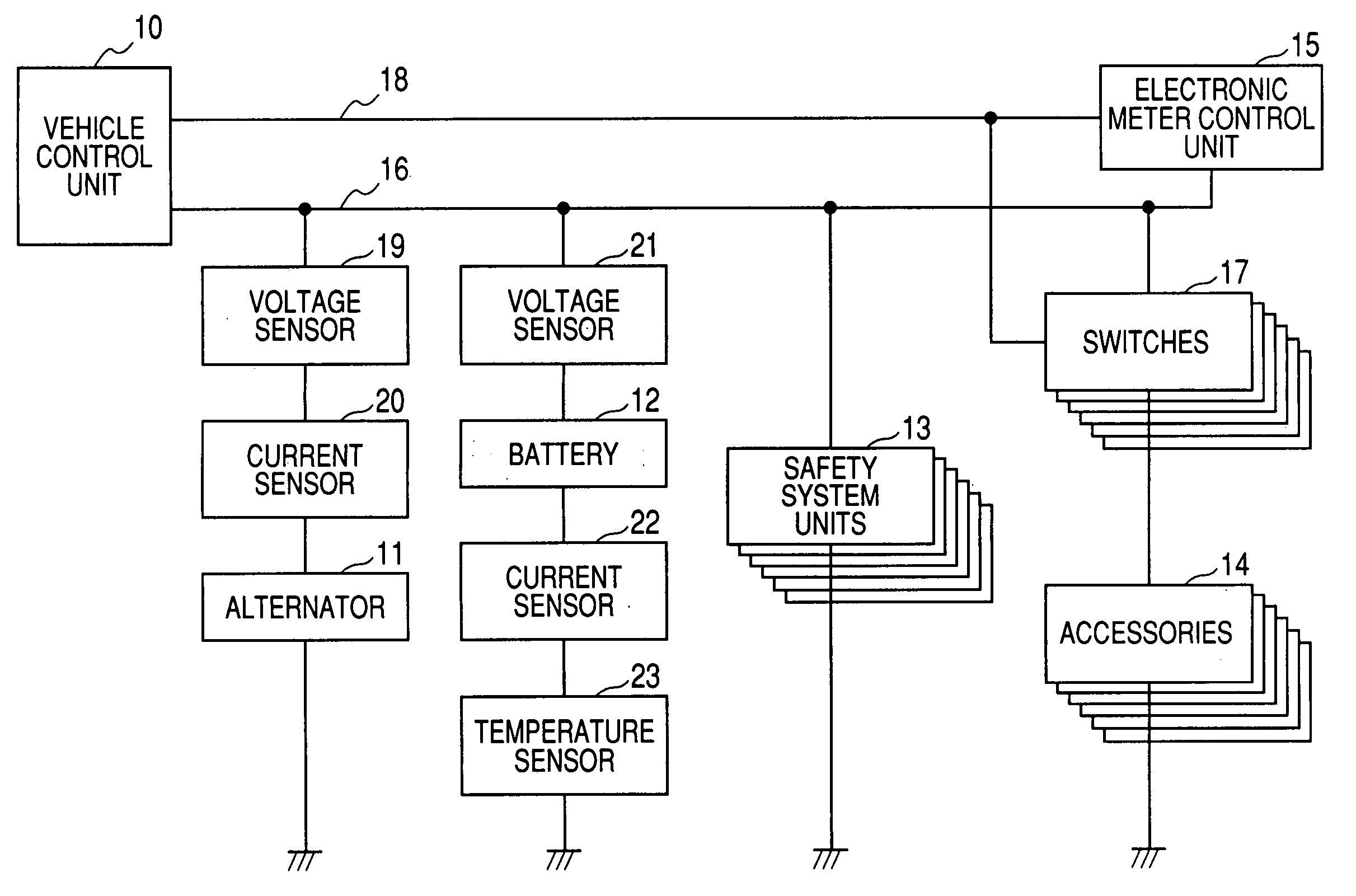
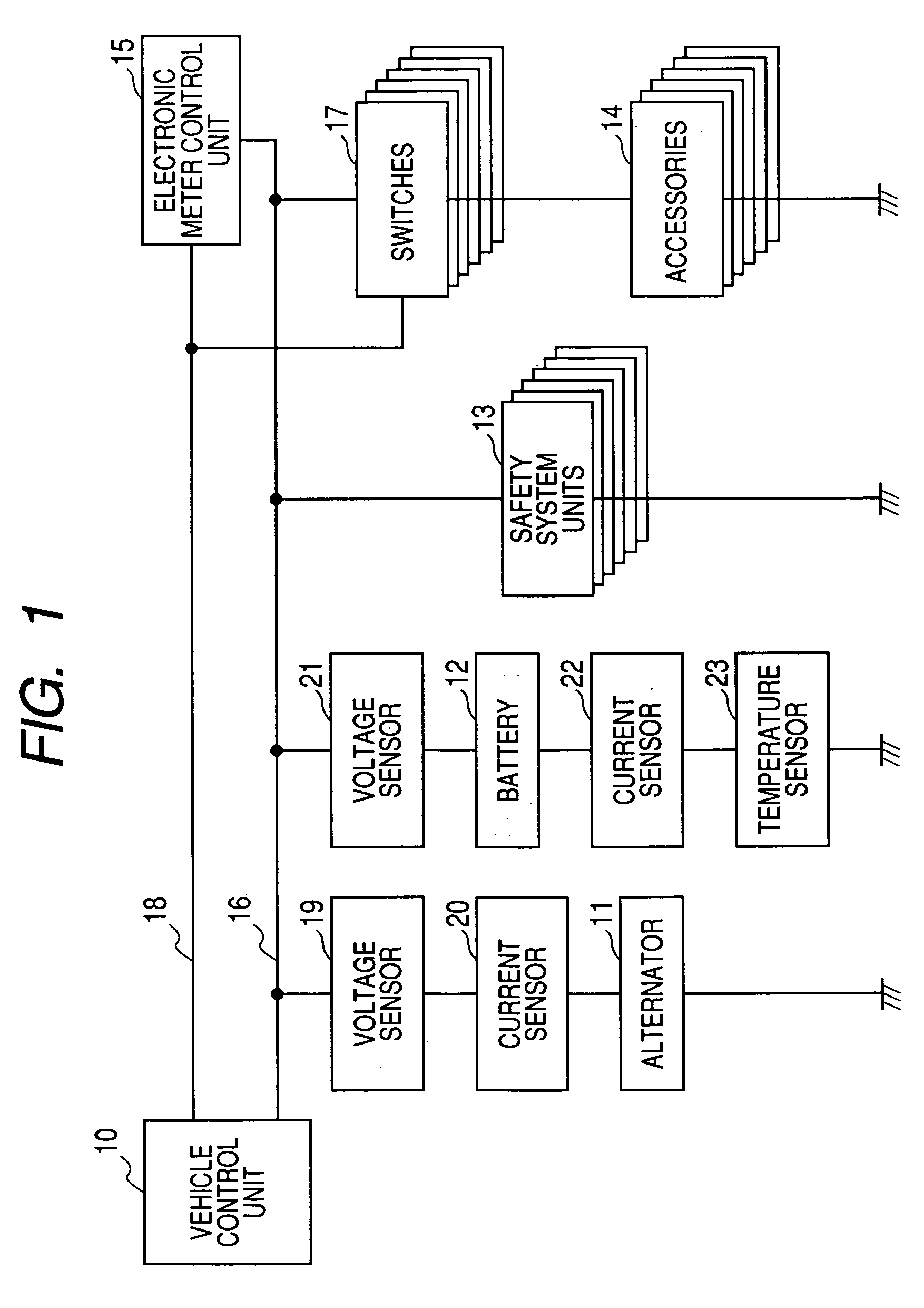
[0043]Firstly, a system configuration of a vehicle control system will be described. As shown in FIG. 1, a vehicle control system includes a vehicle control unit 10 having an economical running function, and an alternator 11 for generating an alternating current while an engine is in operation, a battery 12 for providing a power supply to electric equipments, safety system units 13, accessories 14 and an electronic meter control unit 15 are connected to the vehicle control unit 10 via a power supply line 16. The accessories 14 are connected to the power supply line 16 via switches 17 which can interrupt a power supply to the accessories 14. In addition, the switches 17 and the electronic meter control unit 15 are connected to the vehicle control unit 10 via a signal line 18.

[0044]A voltage sensor 19 for detecting a voltage and a current sensor 20 for detecting a ...


PUM


Abstract

A battery supplies electric power to electric equipments of the vehicle. An alternator generates the electric power and charges the battery when an engine of the vehicle is operated. An economical running control section is operable to perform an economical running in which the engine is automatically stopped when the vehicle is in a predetermined engine stopping condition and the engine is automatically restarted when the vehicle is in a predetermined engine restarting condition. A calculate section is operable to calculate an available current value which is available to supply to the electric equipments from the battery. A feed limiting section is operable to limit to supply the electric power to the electric equipments from the battery. The economical running control section controls the economical running based on a total value of necessary current values which are necessary for the respective electric equipments and the available current value. The feed limiting section limits to supply the electric power to the electric equipments from the battery based on the total value of the necessary current values and the sum of the available current value and a generated current value of the alternator.

Description

[0001]The disclosures of Japanese Patent Application No. 2006-012636 filed on Jan. 20, 2006 including specification, drawings and claims are incorporated herein by reference in its entirety.BACKGROUND OF THE INVENTION[0002]The present invention relates to a vehicle control unit and a vehicle control method, and more particularly to a vehicle control unit and a vehicle control method for controlling a vehicle having a battery which supplies electric power to electric equipments of the vehicle and an alternator which generates the electric power and charges the battery when an engine of the vehicle is operated and an economical running control section operable to perform an economical running in which the engine is automatically stopped when the vehicle is in a predetermined engine stopping condition and the engine is automatically restarted when the vehicle is in a predetermined engine restarting condition.[0003]There are vehicles on which an economical running system is installed. T...

Claims


Application Information

Patent Timeline
IPC IPC(8): B60L1/00
CPCB60K1/00B60R16/03F02N11/0818F02N11/0862Y02T10/48F02N2200/063F02N2200/064F02N2200/0809F02N2200/062Y02T10/40Y10S903/903
Inventor YAMAGUCHI, KAZUHI
Owner FUJITSU GENERAL LTD
Learn More