Thin film emitter-absorber apparatus and methods

Active Publication Date: 2007-07-26
FLIR SURVEILLANCE
View PDF31 Cites 58 Cited by
  • Summary
  • Abstract
  • Description
  • Claims
  • Application Information

AI Technical Summary

Benefits of technology

[0006] What is needed is a simple, thin, wavelength selective surface capable of providing a tunable reflection or absorption

Problems solved by technology

Unfortunately, such structures can be complicated and relatively thick, depending upon the selected dielectric materials and wavelength of operation, par

Method used


Image

  • Thin film emitter-absorber apparatus and methods
  • Thin film emitter-absorber apparatus and methods
  • Thin film emitter-absorber apparatus and methods

Examples


Embodiment Construction

[0037] A description of preferred embodiments of the invention follows.

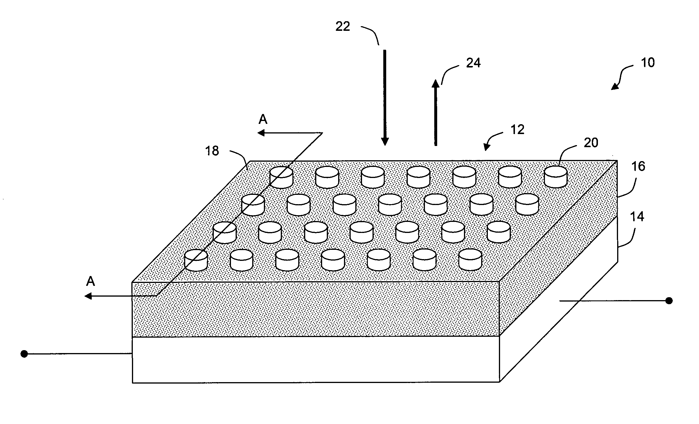
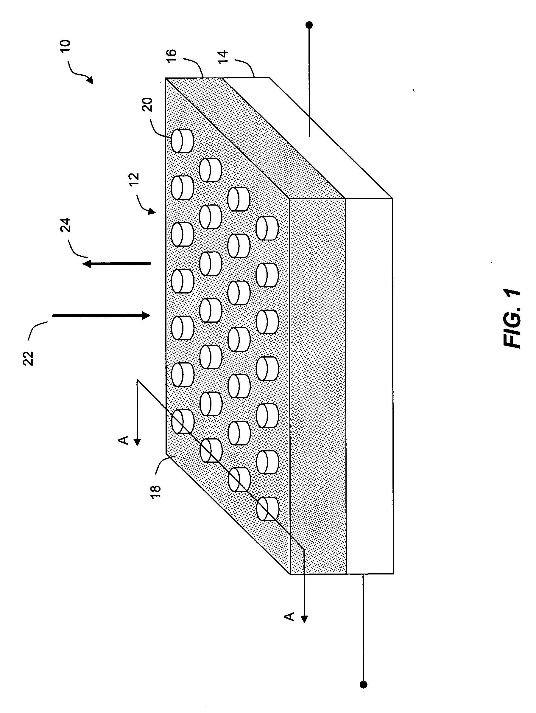
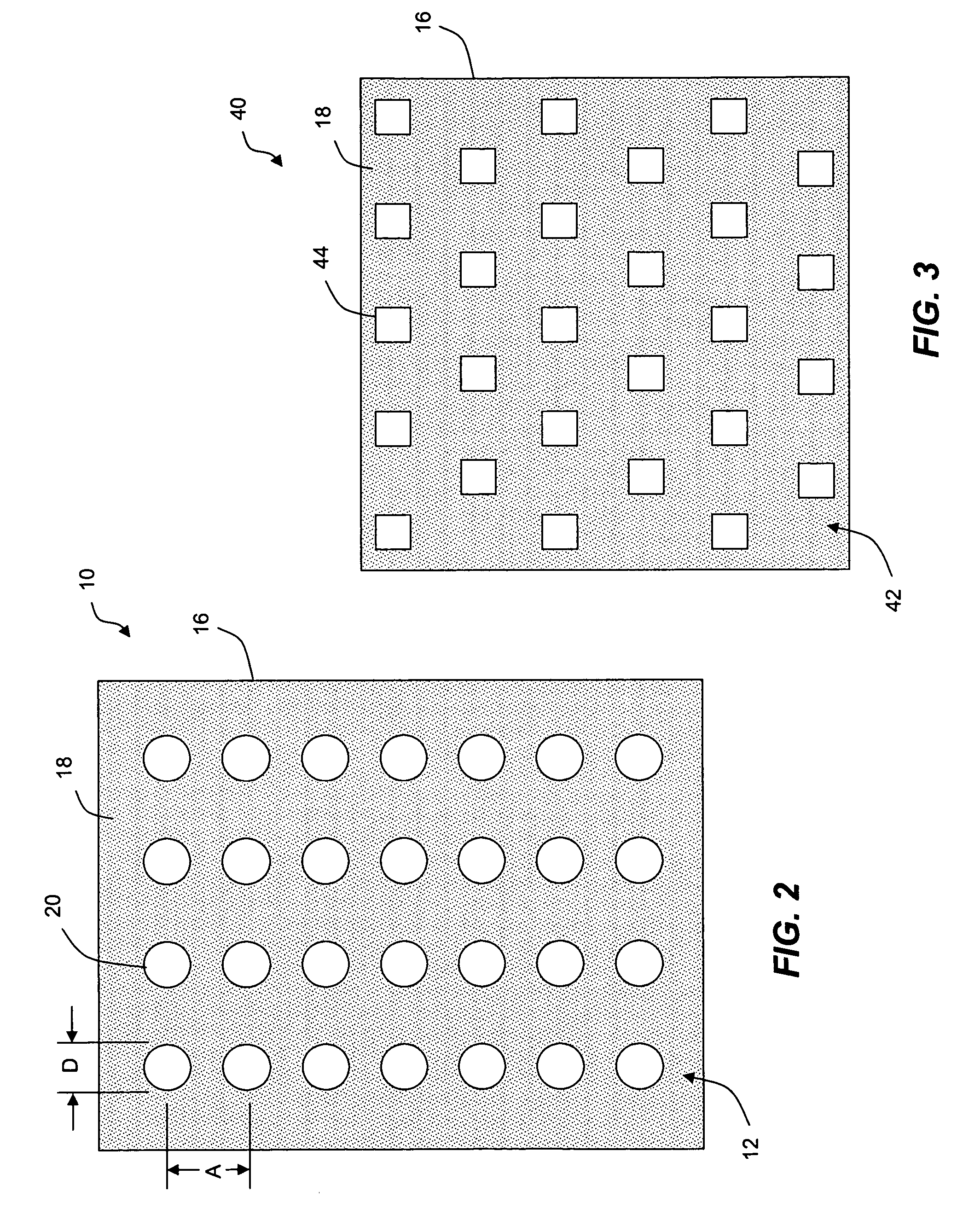
[0038] An exemplary embodiment of a wavelength selective surface 10 is shown in FIG. 1. The wavelength selective surface 10 includes at least three distinguishable layers. The first layer is an electrically conductive outer or surface layer 12 including an arrangement of surface elements 20. The surface elements 20 of the outer layer 12 are disposed at a height above an inner layer including a continuous electrically conductive sheet, or ground layer 14. The arrangement of surface elements 20 and ground layer 14 is separated by an intermediate layer 16 disposed therebetween. At least one function of the intermediate layer 16 is to maintain a physical separation between the arrangement of surface elements 20 and the ground layer 14. The intermediate layer 16 also provides electrical isolation between the two electrically conductive layers 12, 14.

[0039] In operation, wavelength selective surface 10 is exposed to ...


PUM


Abstract

Methods and apparatus for providing a tunable absorption-emission band in a wavelength selective device are disclosed. A device for selectively absorbing incident electromagnetic radiation includes an electrically conductive surface layer including an arrangement of multiple surface elements. The surface layer is disposed at a nonzero height above a continuous electrically conductive layer. An electrically isolating intermediate layer defines a first surface that is in communication with the electrically conductive surface layer. The continuous electrically conductive backing layer is provided in communication with a second surface of the electrically isolating intermediate layer. When combined with an infrared source, the wavelength selective device emits infrared radiation in at least one narrow band determined by a resonance of the device. In some embodiments, the device includes a control feature that allows the resonance to be selectively modified. The device has broad applications including gas detection devices and infrared imaging.

Description

RELATED APPLICATIONS [0001] This application is claims the benefit of priority under 35 U.S.C. §119 from U.S. Provisional Application Ser. No. 60 / 749,468, filed on Dec. 12, 2005, the contents of which are incorporated herein by reference in their entirety.FIELD OF THE INVENTION [0002] The present invention relates generally to reflector and emitter-absorber structures, and more particularly to thin film reflector and emitter-absorber structures formed using multiple conductive elements over a ground plane. BACKGROUND OF THE INVENTION [0003] Frequency selective surfaces can be provided to selectively reduce or enhance reflections from incident electromagnetic radiation. Such surfaces are often employed in signature management applications to reduce radar returns. These applications are typically employed within the radio frequency portion of the electromagnetic spectrum. [0004] As modem radar systems are often equipped with different and even multiple frequency bands, such signature ...

Claims


Application Information

Patent Timeline
IPC IPC(8): G01S13/00
CPCG01J3/108G01N21/3504G02F1/19G02F2201/083G02F2201/307H01Q15/006G02F2203/055G02F2203/10G02F2203/11G02F2203/48H01Q15/0066G02F2202/10G02F2202/30G02F2203/15G02F1/21
Inventor PUSCASU, IRINAJOHNSON, EDWARD A.
Owner FLIR SURVEILLANCE
Why Eureka
Try Eureka