
Plasmon-photon coupled optical devices

a technology of optical devices and plasmons, applied in the direction of optics, discharge tubes/lamp details, instruments, etc., can solve the problems of limiting the further development of near-field optical devices, the low transmittivity of light waves through extremely small diameter holes, and the wavelength of incident light is smaller than the wavelength of incident ligh

Inactive Publication Date: 2006-09-19
CLEMSON UNIV RES FOUND
View PDF20 Cites 47 Cited by
  • Summary
  • Abstract
  • Description
  • Claims
  • Application Information

AI Technical Summary

Benefits of technology

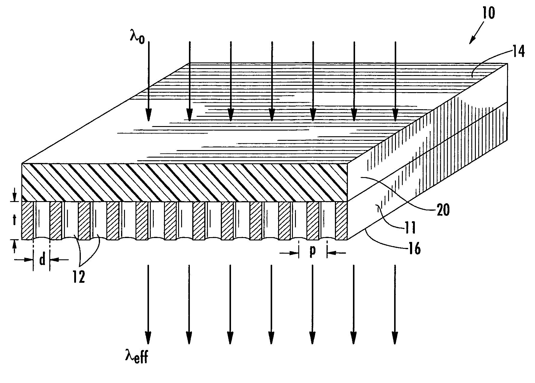
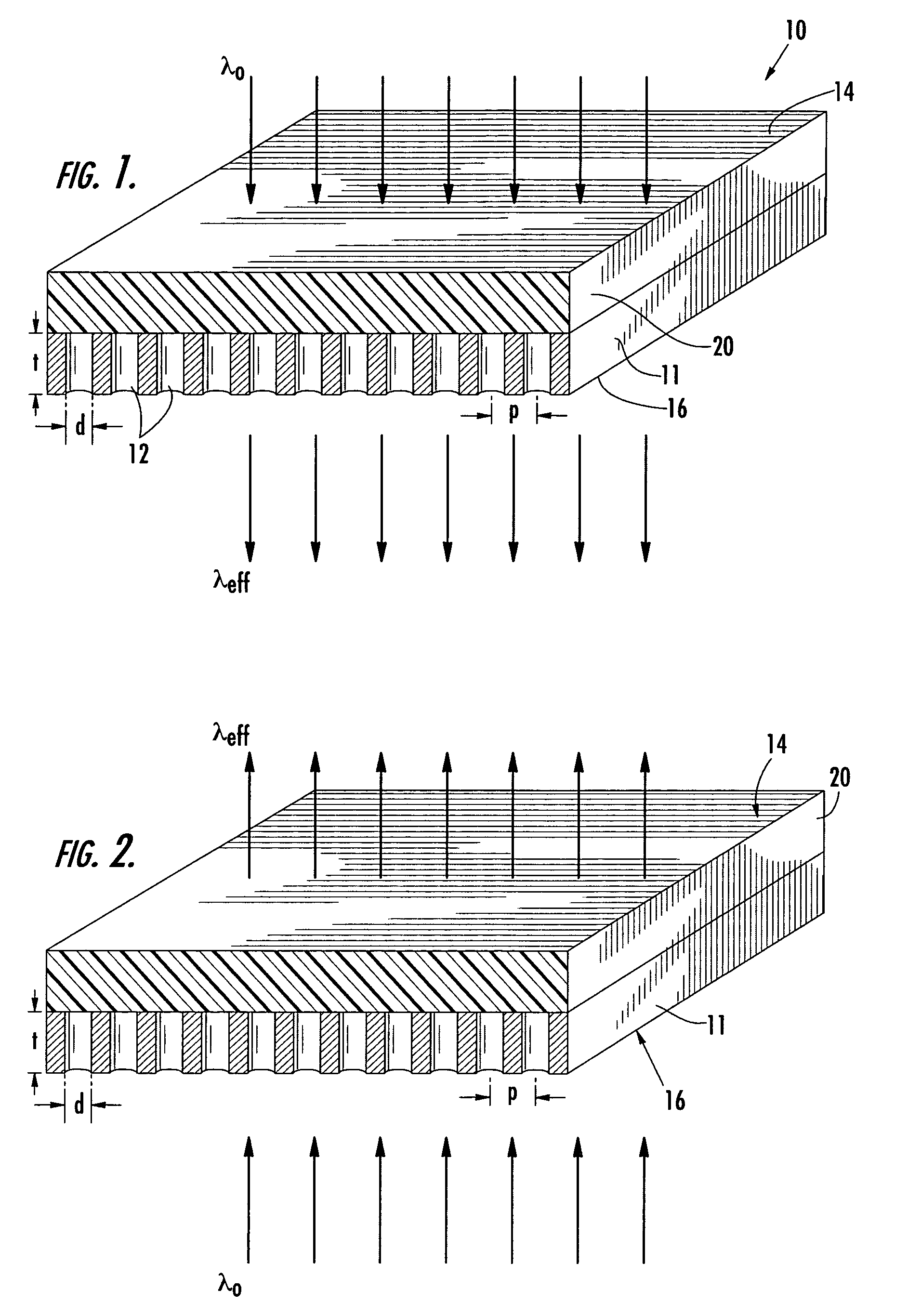
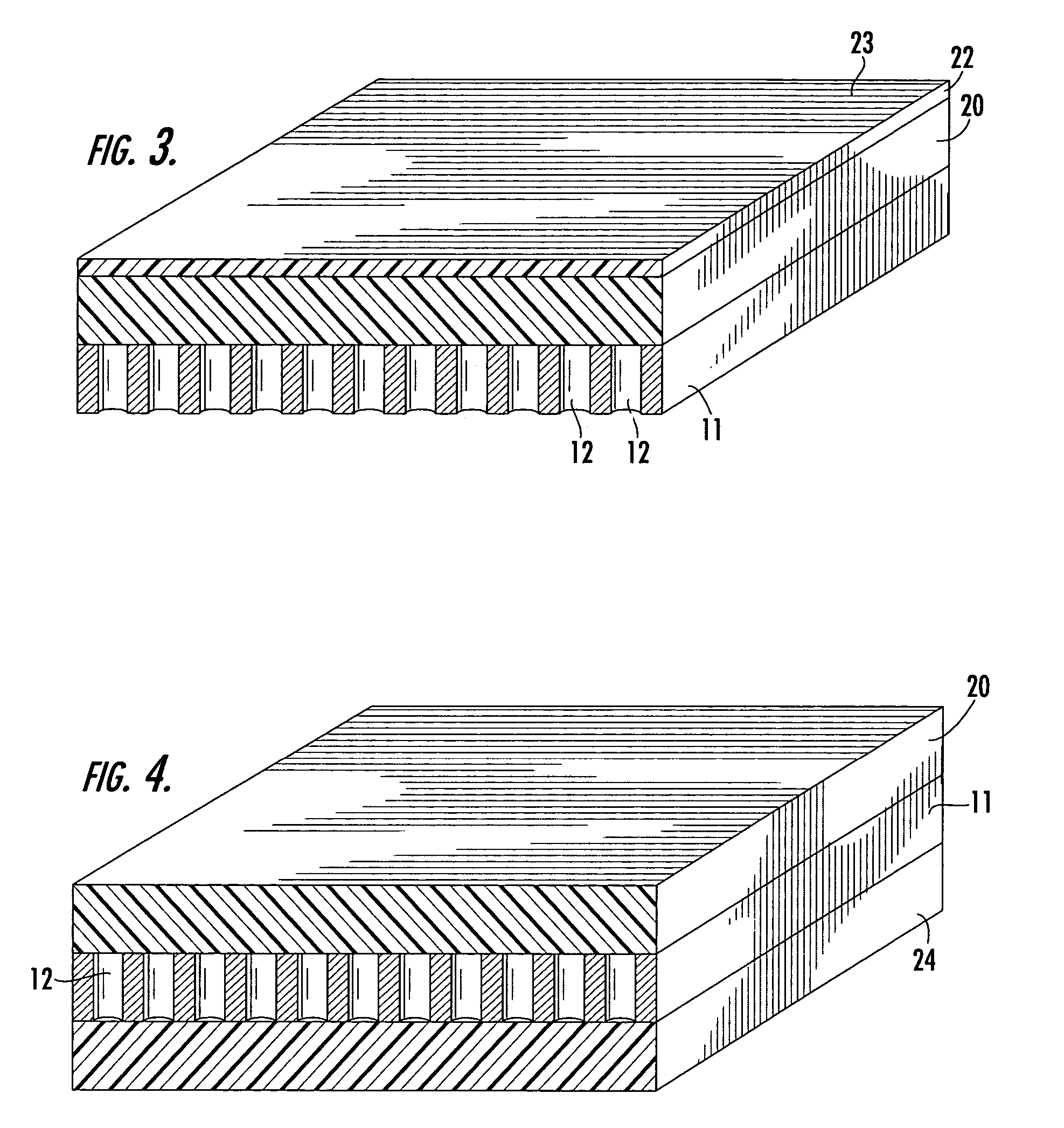
The present invention is about optical devices that use a film with a periodic array of apertures to excite surface plasmons. The film can be made of a material that can give rise to surface plasmons, such as metal or heavily doped semiconductor. The refractive index of the material can vary based on the characteristics of the incident light. The film can have a single aperture or an array of apertures that can be designed to have a specific periodicity and can be used to filter light or modulate its transmission. The devices can be used for optical switching, filtering, and modulation. The invention also includes a method for making the film with a periodic array of apertures.

Problems solved by technology

For many years, the low transmittivity of light waves through extremely small diameter holes, smaller than the wavelength of the incident light, was a limiting factor to the further development of near-field optical devices.

Method used


Image

  • Plasmon-photon coupled optical devices
  • Plasmon-photon coupled optical devices
  • Plasmon-photon coupled optical devices

Examples


Embodiment Construction

[0026]Reference will now be made in detail to various embodiments of the invention, one or more examples of which are set forth below. Each embodiment is provided by way of explanation of the invention, not limitation of the invention. In fact, it will be apparent to those skilled in the art that various modifications and variations may be made in the present invention without departing from the scope or spirit of the invention. For instance, features illustrated or described as part of one embodiment, may be used in another embodiment to yield a still further embodiment. Thus, it is intended that the present invention cover such modifications and variations as come within the scope of the appended claims and their equivalents.

[0027]In one embodiment, the present invention is directed to optical devices in which the nature of light transmitted through the device can be dependent upon the nature of the incident light, i.e., self-regulated transmissive devices. More specifically, the ...


PUM

PropertyMeasurementUnit
diameteraaaaaaaaaa
distanceaaaaaaaaaa
aspect ratioaaaaaaaaaa

Abstract

The present invention is directed to optical devices. More specifically, the disclosed devices include a film defining a periodic array of surface elements so as to give rise to surface plasmon polaritons. The film also includes at least a single aperture having a diameter less than the wavelength of light. In one embodiment, the surface elements can be an array of anisotropic apertures and the films can act as a polarizer. The disclosed devices can also include a material having a variable refractive index substantially adjacent to the metal film. For example, the refractive index of the adjacent material can vary according to some characteristic of the light incident to the device, for instance, the intensity or the angle of incidence of the light. In this embodiment, resonant coupling of incident light with the SPP, and hence transmittivity of the device, can depend upon the nature of incident light. The disclosed devices can be useful in, for example, remote polarizers, polarization mode dispersion, isolators, multi-color displays, switches, such as can be controlled according to incident sunlight, or optical filters, such as for eye protection devices, filtering out possibly harmful light.

Description

BACKGROUND OF THE INVENTION[0001]Over the last century, mankind has developed a growing understanding of the nature of light. This growing understanding has led to an increasing ability to harness and control light, which has in turn led to improvements in a wide variety of different technologies. For instance, the ability to control photons has led to improvements in communications, such as through the development of fiber optics; improvements in opto-electronics, such as through the development of photo-voltaic cells; as well as the development of near-field optics, a field of study dedicated to the utilization of near-field light, which is the light created around the periphery of an object emitting or being illuminated by light. The study of near-field light has brought about the development of and continuing improvements to many optical devices including many different types of imaging devices as well as optical scanners, filters, switches, modulators, and the like.[0002]For ma...

Claims


Application Information

Patent Timeline
Patent Type & Authority Patents(United States)
IPC IPC(8): G02F1/03G02F1/00G02F1/01H01J3/14G02F1/1335G02F1/35
CPCG02F1/353G02F1/0338G02F2203/52G02F2203/10G02F2202/32
Inventor BALLATO, JOHNCARROLL, DAVID L.DIMAIO, JEFFREY R.
Owner CLEMSON UNIV RES FOUND
Learn More