Frequency converter

a frequency converter and converter technology, applied in the field of frequency converters, can solve the problems of increasing the cost of components, and increasing the power consumption of the structure afterward, so as to reduce the loss

Inactive Publication Date: 2007-07-26
SAMSUNG ELECTRONICS CO LTD
View PDF0 Cites 20 Cited by
  • Summary
  • Abstract
  • Description
  • Claims
  • Application Information

AI Technical Summary

Benefits of technology

[0015] Accordingly, the present invention has been designed to solve the above and other problems. Therefore, it is an object of the present invention to provide a frequency converter that can further reduce loss while limiting the frequency of an intermediate frequency (IF) signal to a low frequency in a heterodyne scheme.

Problems solved by technology

However, there are the following technical problems as well as a problem of an increase in the cost of components due to the broad band when the heterodyne scheme is applied to the broad band.
Thus, when the signal SB2 is a target signal to be output, the image frequency signal interferes with the associated target signal.
For this reason, there is a problem in that power consumption increases in a structure after an IF stage.
There is a problem in that the image frequency signal must be able to be suppressed using a BPF of a steep characteristic or at least two BPFs since the requirements of the BPF 1003 and the BPF 1105 are strict even when the frequency of the IF signal is as low as possible.
However, when the multiple BPFs of the steep characteristic are provided, products increases in terms of size and / or cost.
Since a passive polyphase filter is constructed with a RC circuit, loss is large.
For this reason, there is a problem in that the loss due to the polyphase filter 1204 is added to the loss due to the BPF 1205 of the IF stage when a real IF signal is output.

Method used


Image

  • Frequency converter
  • Frequency converter
  • Frequency converter

Examples


Embodiment Construction

[0037] A downconverter serving as a frequency converter for frequency-converting a radio frequency (RF) signal to an intermediate frequency (IF) signal less than a frequency of the RF signal and an upconverter serving as a frequency converter for frequency-converting an IF signal to an RF signal greater than a frequency of the IF signal in accordance with the present invention will be described in detail herein below with reference to the accompanying drawings. In the following description, detailed descriptions of functions and configurations incorporated herein that are well known to those skilled in the art are omitted for clarity and conciseness.

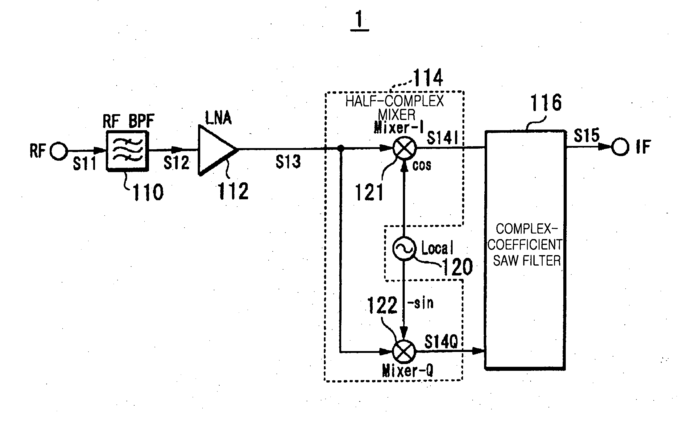
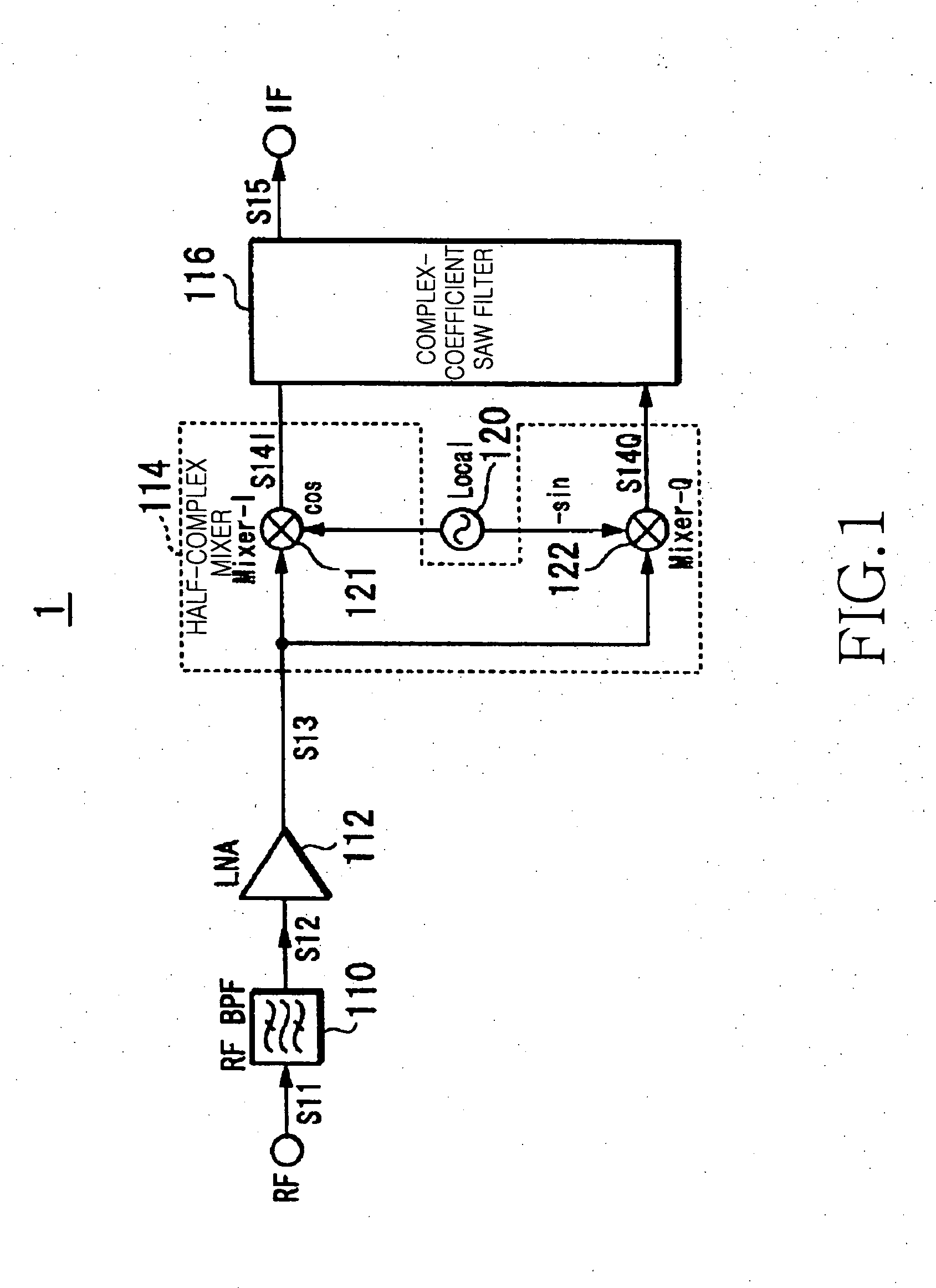
[0038]FIG. 1 is a block diagram illustrating a downconverter 1 in accordance with the present invention. The downconverter 1 is provided with a band path (or pass) filter (BPF) 110, a low noise amplifier (LNA) 112, a local oscillator 120, a half-complex mixer 114, and a complex-coefficient surface acoustic wave (SAW) filter 116. The dow...


PUM


Abstract

A BPF outputs a real RF signal by suppressing a band out of an RF signal frequency band in a received signal. A local oscillator outputs a complex local signal with a predetermined frequency. A half-complex mixer performs frequency conversion by multiplying the real RF signal by a real part of the local signal, performs frequency conversion by multiplying the real RF signal by an imaginary part of the local signal, and outputs a complex signal separated by the predetermined frequency from a frequency of the real RF signal. A complex-coefficient SAW filter performs a convolution integral on an impulse response generated by an even function for a real part of the complex signal, performs a convolution integral on an impulse response generated by an odd function for an imaginary part of the complex signal, and outputs a real signal by suppressing one side of a positive or negative frequency.

Description

PRIORITY [0001] This application claims priority under 35 U.S.C. § 119 to applications entitled “Frequency Converter” filed in the Japan Patent Office on Dec. 20, 2005 and assigned Serial No. 2005-366732 and in the Korean Intellectual Property Office on Nov. 22, 2006 and assigned Serial No. 2006-115265, the contents of each of which are incorporated herein by reference. BACKGROUND OF THE INVENTION [0002] 1. Field of the Invention [0003] The present invention relates to a frequency converter for use in a wireless transceiver. [0004] 2. Description of the Related Art [0005] Wireless communicators function both as a receiver and a transmitter like a mobile phone. The receiver, i.e., a downconverter, receives a radio frequency (RF) signal with conversation content and data communication content and converts the received RF signal to a frequency to be input to a demodulator. Further, as a front-end scheme for selecting a target signal in the downconverter, there is a heterodyne scheme fo...

Claims


Application Information

Patent Timeline
Patent Type & Authority Applications(United States)
IPC IPC(8): H04N5/455
CPCH04N5/4446H03D3/007
Inventor KISHI, TAKAHIKO
Owner SAMSUNG ELECTRONICS CO LTD
Why Eureka
Try Eureka