Optical device

Inactive Publication Date: 2007-07-26
SEIKO EPSON CORP
View PDF4 Cites 15 Cited by
  • Summary
  • Abstract
  • Description
  • Claims
  • Application Information

AI Technical Summary

Benefits of technology

[0011]The present invention has been made in view of the above drawbacks. It is, therefore, an object of the present invention to provide an optical device, an opt

Problems solved by technology

Thus, if distances between the drive electrodes and the detection electrodes are short, then a coupling capacitance between the

Method used


Image

  • Optical device
  • Optical device
  • Optical device

Examples


Example

[0051]An optical device, an optical tunable filter, an optical tunable filter module, and an optical spectrum analyzer according to embodiments of the present invention will be described below with reference to FIGS. 1 to 11. Like or corresponding parts are denoted by like or corresponding reference numerals throughout drawings, and will not be described below repetitively.

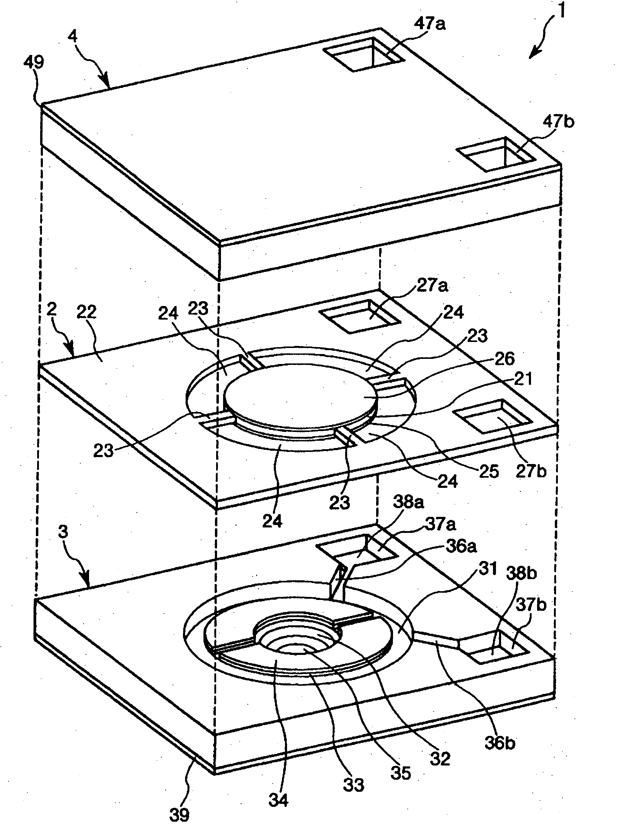
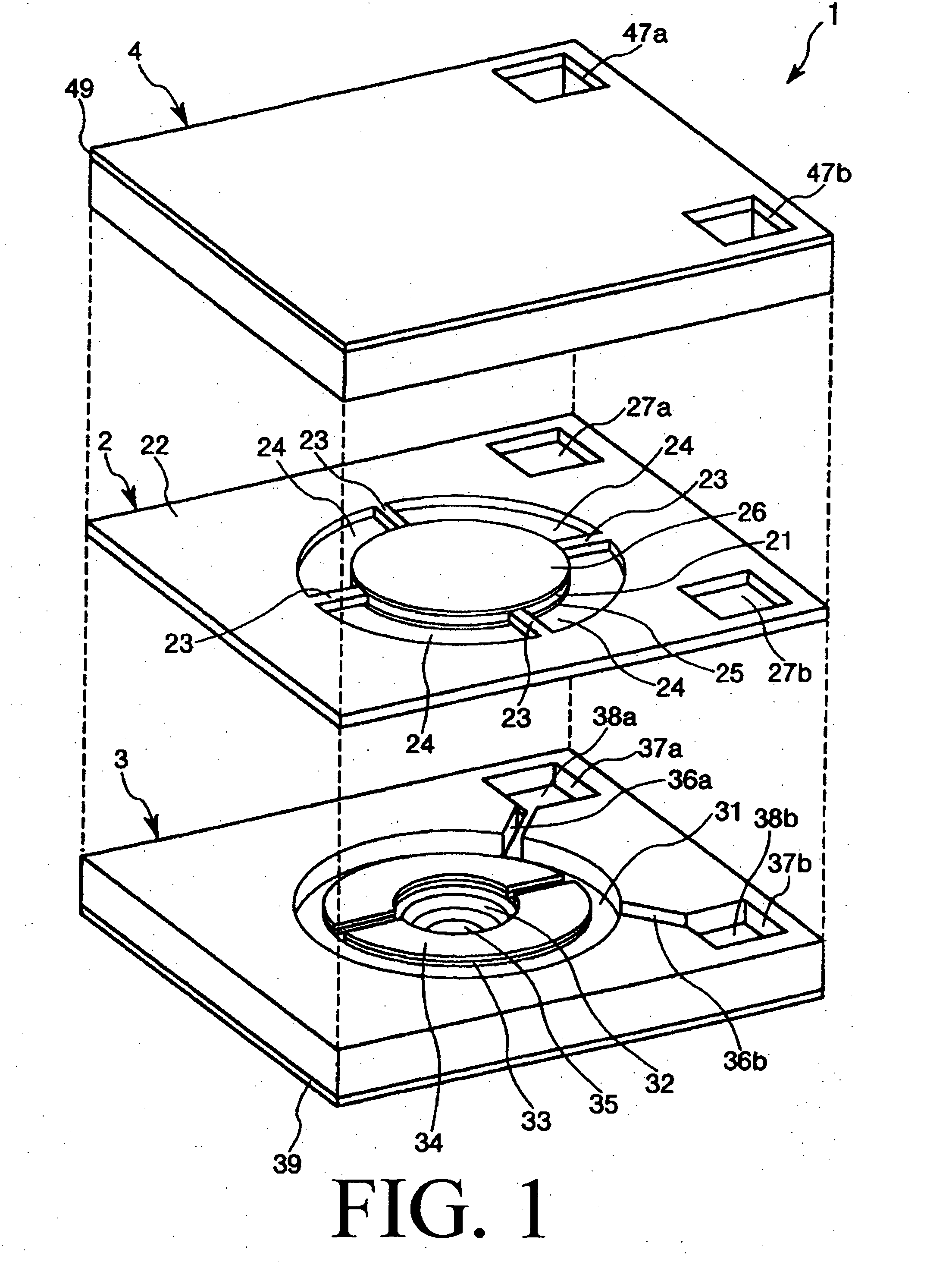
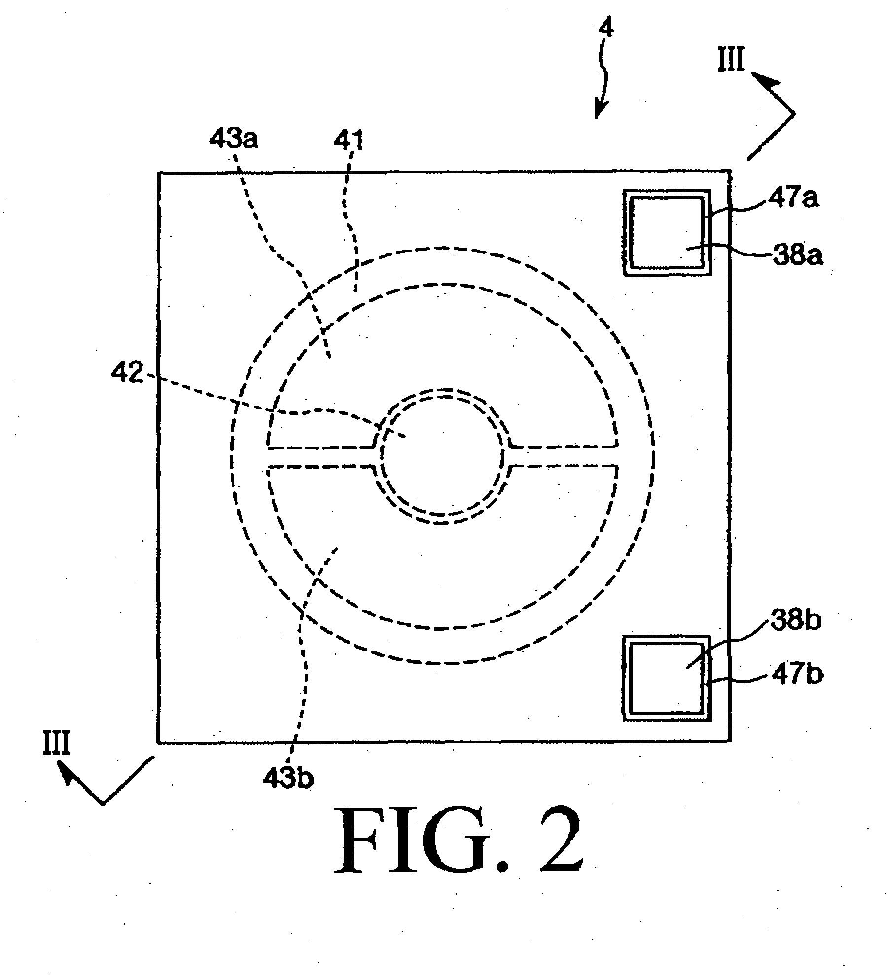
[0052]FIG. 1 is an exploded perspective view showing an optical device (optical tunable filter) according to an embodiment of the present invention. FIG. 2 is a plan view showing the optical device shown in FIG. 1. FIG. 3 is a cross-sectional view taken along line III-III of FIG. 2. FIG. 4 is a view explanatory of electrodes in the optical device shown in FIG. 1. FIG. 5 is a block diagram showing a configuration of a control system in the optical device shown in FIG. 1. In the following description, the upper and lower sides in FIG. 1 will be referred to as “upper” and “lower,” respectively. The near, far, right, ...


PUM

PropertyMeasurementUnit
Forceaaaaaaaaaa
Sizeaaaaaaaaaa
Shapeaaaaaaaaaa

Abstract

An optical device includes a movable portion and a fixed portion having a first light reflection portion. The movable portion has a second light reflection portion facing the first light reflection portion with a first gap. The first and second light reflection portions are configured to reflect light repeatedly between the first and second light reflection portions so as to cause interference and emit light having a wavelength corresponding to a size of the first gap. The optical device also includes a first electrode portion fixed to the fixed portion so as to face a surface of the movable portion near the first light reflection portion with a second gap between the movable portion and the first electrode portion. The optical device has a second electrode portion fixed to the fixed portion so as to face another surface of the movable portion with a third gap between the movable portion and the second electrode portion. One of the first and second electrode portions serves as a detection electrode for detecting a capacitance between the movable portion and the detection electrode. Another of the first and second electrode portions serves as a drive electrode. The optical device includes a circuit operable to generate a potential difference between the movable portion and the drive electrode so as to generate an electrostatic attraction force therebetween for changing a position and/or a posture of the movable portion.

Description

CROSS-REFERENCE TO RELATED APPLICATION[0001]This application claims priorities to Japanese Patent Applications No. 2006-011549 filed on Jan. 19, 2006 and No. 2006-277017 filed on Oct. 10, 2006 which are hereby expressly incorporated by reference herein in their entirety.BACKGROUND OF THE INVENTION[0002]1. Field of the Invention[0003]The present invention relates to an optical device, an optical tunable filter, an optical tunable filter module, and an optical spectrum analyzer.[0004]2. Description of the Related Art[0005]For example, an optical tunable filter for separating only light having a specific wavelength from light having a plurality of wavelengths has been known as an optical device. For instance, U.S. Pat. No. 6,747,775 (Patent Document 1) discloses such an optical tunable filter.[0006]An optical tunable filter disclosed by Patent Document 1 has a movable portion in the form of a plate, support substrates, and reflection films formed on opposed surfaces of the movable port...

Claims


Application Information

Patent Timeline
IPC IPC(8): G02B1/11B81B3/00G02B6/35G02B26/00
CPCG02B26/001
Inventor NAKAMURA, RYOSUKE
Owner SEIKO EPSON CORP
Why Eureka
Try Eureka