Screw member having two different thread angles formed on a sharp-edged thread

Inactive Publication Date: 2007-07-26
EASYLINK IND
View PDF33 Cites 1 Cited by
  • Summary
  • Abstract
  • Description
  • Claims
  • Application Information

AI Technical Summary

Benefits of technology

[0010]The primary objective of this invention is to provide a screw member having two different thread angles formed on a sharp-edged thread for easy drilling operation. A first thread angle of a first thread section is proxima

Problems solved by technology

In drilling operation, the primary problem with such a conventional screw member is due to the fact that the sharp-edged thread of the thread portion 2 functions as a blade to cut the material of the plank so as to allow insertion of the screw shank portion 1 into the plank.
The problem with the greater exertions during drilling the plank is a tilt of the screw member to the surface of

Method used


Image

  • Screw member having two different thread angles formed on a sharp-edged thread
  • Screw member having two different thread angles formed on a sharp-edged thread
  • Screw member having two different thread angles formed on a sharp-edged thread

Examples


Embodiment Construction

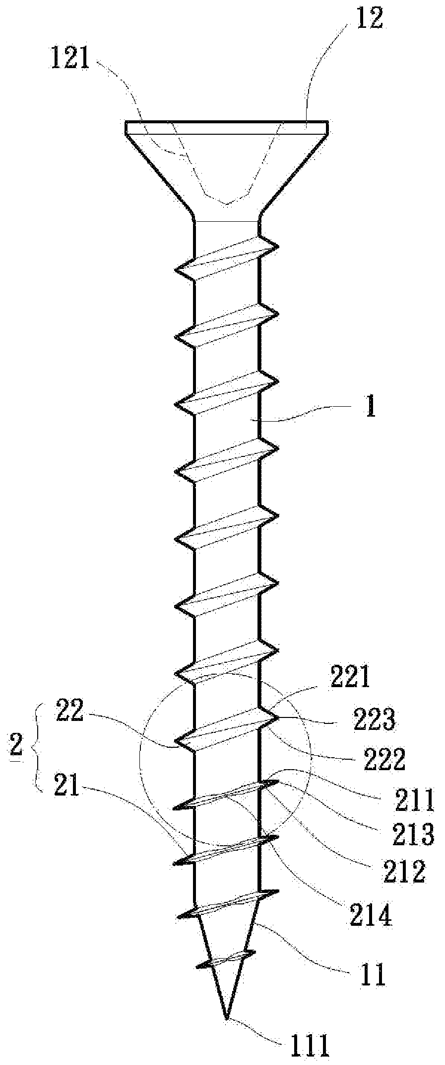
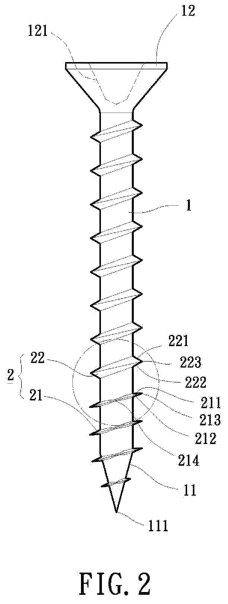
[0025]Referring initially to FIG. 2, a side elevational of a screw member having different thread angles in accordance with a first embodiment of the present invention is illustrated. The screw member includes a screw shank portion 1 and a thread portion 2 provided thereon. Construction of the screw shank portion 1 shall now be described in further detail, with reference to FIG. 2. The screw shank portion 1 is upright in form and presents a shank body. The screw shank portion 1 has a bottom end formed with a tapered section 11, and a top end formed with a screw head portion 12. The tapered section 11 is further formed with a sharp tip 111 at its distal end for digging a surface of a plank 3 (as best shown in FIG. 5) or the like. In drilling operation, the tapered section 11 may cause an initially drilling effect on the surface of the plank 3 by means of an appropriate pressing force. Preferably, the screw head portion 12 has a recessed structure of an actuating slot or socket 121 fo...


PUM


Abstract

A screw member comprises a screw shank portion and a thread portion provided thereon. The screw shank portion has a bottom end formed with a tapered section, and a top end formed with a screw head portion. The thread portion is provided on an outer circumference of the screw shank portion. The thread portion includes a first thread section proximate the tapered section, and a second thread section proximate the screw head portion. The first thread section has a first thread angle of a sharp-edged thread smaller than a second thread angle of the second thread section such that the first thread section is easier to cut a rigid material.

Description

BACKGROUND OF THE INVENTION [0001]1. Field of the Invention[0002]The present invention relates to a screw member having two different thread angles of a sharp-edged thread. More particularly, the present invention relates to the two different thread angles of the screw member formed on the sharp-edged thread for easy drilling operation.[0003]2. Description of the Related Art[0004]A conventional screw member, as shown in FIG. 1, includes a screw shank portion 1 and a thread portion 2 provided thereon. Typically, the screw shank portion 1 is of a rod-like or stick-like member having a bottom end formed with a tapered section 11, and a top end formed with a screw head portion 12. The tapered section 11 is further formed with a sharp tip 111 for digging a surface of a wood plank, an object or a sheetmetal. Generally, the screw head portion 12 has a recessed structure of an actuating slot or socket 121 for receiving a tip of a tool member (not shown) in screwing operation. The actuating ...

Claims


Application Information

Patent Timeline
IPC IPC(8): F16B33/00
CPCF16B25/0031F16B25/0057F16B25/0047
Inventor TSAU, TIAN-FU
Owner EASYLINK IND
Why Eureka
Try Eureka