High Frequency receiver, integrated circuit used therefor, portable equipment using them, transmitter used therefor, and manufacturing method thereof

a technology of integrated circuits and receivers, applied in the field of high frequency receivers, to achieve the effect of stably receiving, rapid removal of interference from transmission signals, and improved performan

Inactive Publication Date: 2007-07-26
PANASONIC CORP
View PDF10 Cites 26 Cited by
  • Summary
  • Abstract
  • Description
  • Claims
  • Application Information

AI Technical Summary

Benefits of technology

[0020] Thus, even if the transmission signal input from the antenna is changed, the transmission signal can be cancelled. Consequently, it is possible to provide a high frequency receiver capable of stably receiving the transmission signal even if it is changed, and the like.
[0021] Furthermore, since a signal input to the input terminal is distributed so as to control a level regulator, it is possible to follow the change of the amplitude rapidly. Therefore, the interference due to a transmission signal can be rapidly removed and improved. Furthermore, a noise signal of an oscillator included in the transmission signal is input to a distributed transmission signal input terminal. Even if the frequency of the noise component is a frequency within the receive frequency band, a signal of the noise component can be cancelled.

Problems solved by technology

The distributed transmission signal is included at least in a transmission signal and is interfering in a high frequency receiving device.

Method used


Image

  • High Frequency receiver, integrated circuit used therefor, portable equipment using them, transmitter used therefor, and manufacturing method thereof
  • High Frequency receiver, integrated circuit used therefor, portable equipment using them, transmitter used therefor, and manufacturing method thereof
  • High Frequency receiver, integrated circuit used therefor, portable equipment using them, transmitter used therefor, and manufacturing method thereof

Examples


first exemplary embodiment

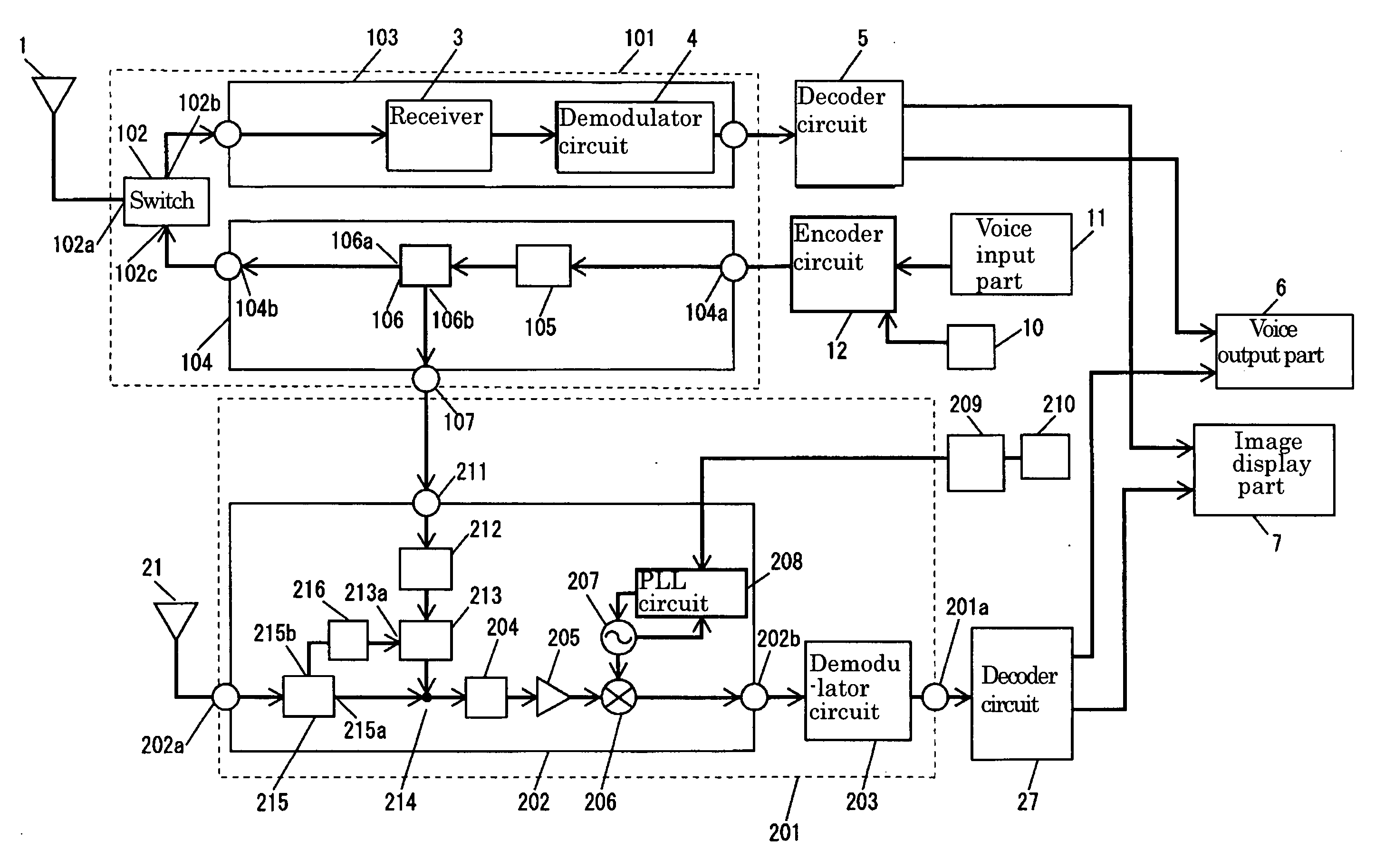
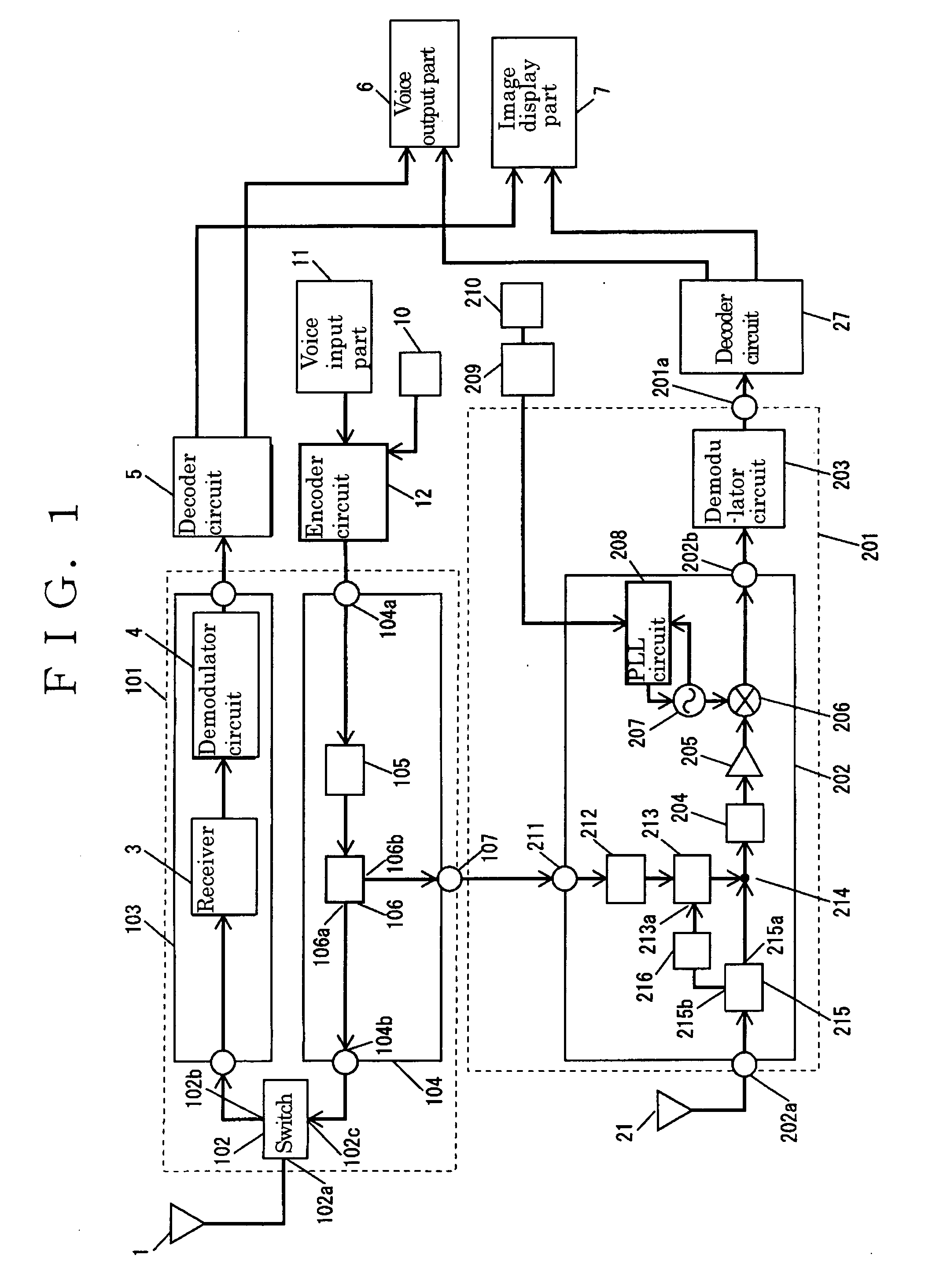
[0064] Hereinafter, a first exemplary embodiment is described with reference to drawings. FIG. 1 is a block diagram showing portable equipment in accordance with the first exemplary embodiment. The same references are given to the same elements as those described in FIG. 12 used in “Background Art” and description therefor is simplified.

[0065] To antenna 1 used as one of transmitting antennas, telephone part 101 is coupled. Telephone part 101 is prepared for transmitting and receiving a GSM mode telephone signal having a frequency of about 880 MHz. Furthermore, telephone part 101 includes antenna switch 102, receiving part 103 and transmitter 104. Antenna 1 is used for both transmitting and receiving signals.

[0066] To input-output terminal 102a of antenna switch 102, antenna 1 is coupled. To output terminal 102b, telephone receiver 3 is coupled. Antenna switch 102 switches a signal between transmission and reception. At the time of reception, a signal received by antenna 1 is outp...

second exemplary embodiment

[0100] Next, a second exemplary embodiment is described with reference to FIG. 3. FIG. 3 is a block diagram showing portable equipment. The same reference numerals are given to the elements as those in FIG. 1 and description therefor is simplified.

[0101] In TV tuner 300 in accordance with the second exemplary embodiment, instead of phase shifter 212 in accordance with the first exemplary embodiment, phase shifter 301 capable of changing phases is used. Phase shifter 301 changes a phase of a distributed transmission signal input to input terminal 301b in accordance with a voltage input to phase control terminal 301a.

[0102] Phase control terminal 301a is coupled to output terminal of control circuit 303 via control terminal 302 of TV tuner 300. Control circuit 303 is used as one of the phase controllers. Control circuit 303 is disposed in high frequency receiver 304 and coupled to control terminal 305 a of level regulator 305 via control terminal 308 of TV tuner 300. To level contro...

third exemplary embodiment

[0115] As described in the first exemplary embodiment, a phase shifter changing phases in a broad band generally has a complicated and large configuration and is expensive. Therefore, in equipment such as portable equipment in which portability is particularly preferential, it is difficult to employ such a configuration.

[0116] Then, in the third exemplary embodiment, instead of phase shifter 301 (FIG. 3) in accordance with the second exemplary embodiment, a phase shifter is configured by using phase shifter 501 (FIG. 5) capable of changing phases in a narrow frequency band.

[0117] Next, the third exemplary embodiment is described with reference to drawings. FIG. 5 is a block diagram showing a TV tuner. The same reference numerals are given to the same elements in FIG. 3 and the description therefor is simplified.

[0118] A receive signal input to input terminal 502a is input to a first input terminal of synthesizer 503 via directional coupler 215. An output signal from synthesizer 5...


PUM


Abstract

A high frequency receiver capable of stably canceling interference by a transmission signal even if a transmission signal input from a TV antenna is changed. Phase shifter (212) for changing a phase of an interfering distributed transmission signal, detector (216) for detecting a level of a transmission signal included in a receive signal input via an antenna, and level regulator (213) for changing a level of the distributed transmission signal in accordance with this level are provided. A signal input via level regulator (213) and phase shifter (212) and a receive signal are synthesized to be input into mixer (206). Since a transmission signal can be cancelled even if a transmission signal input from an antenna is changed, a high frequency receiver can receive a signal stably when a transmission signal is changed.

Description

TECHNICAL FIELD [0001] The present invention relates to a high frequency receiver for receiving a frequency in the vicinity of a transmission signal from a transmitter, an integrated circuit used therefor, portable equipment using them, a transmitter used therefor and a manufacturing method thereof. BACKGROUND ART [0002] A conventional high frequency receiver is described with reference to drawings. FIG. 12 is a block diagram showing portable equipment using a conventional high frequency receiving device. A signal input to telephone antenna 1 is input to an input-output terminal of switch 2. Switch 2 switches a signal between transmission and reception. The signal input to telephone antenna 1 is input to telephone receiver 3 via switch 2, and further converted into an intermediate frequency signal to be output from telephone receiver 3. [0003] The intermediate frequency signal output from telephone receiver 3 is input to demodulator circuit 4. The signal demodulated in demodulator c...

Claims


Application Information

Patent Timeline
Patent Type & Authority Applications(United States)
IPC IPC(8): H04B1/44H04B1/18H04B1/26H04M1/00
CPCH04B1/525H04B1/126H04B15/02
Inventor NODA, MASAAKIKITAGAWA, MOTOYOSHI
Owner PANASONIC CORP
Why Eureka
Try Eureka