Method for matching a model spectrum to a measured spectrum

a technology of measurement spectrum and model spectrum, applied in the direction of electric digital data processing, speed/acceleration/shock measurement devices, instruments, etc., can solve the problem of measuring spectrum when compared to the model spectrum, measurement does not directly provide material data, affecting the intensity of reflected light,

Inactive Publication Date: 2007-07-26
VISTEC SEMICON SYST JENA
View PDF3 Cites 11 Cited by
  • Summary
  • Abstract
  • Description
  • Claims
  • Application Information

AI Technical Summary

Benefits of technology

[0025]The calculation of the new damped model spectrum 20 is then iteratively continued until the percentage change from the old to the new values for LS and LD falls short of a predetermined value, such as about 1%.

Problems solved by technology

These measurements do not directly provide, however, the desired material data, such as the above-mentioned layer thickness.
By overlapping the incident and reflected light beams, an interference results which affects the intensity of the reflected light.
These are caused by interference.
If the reflection spectrum of a thick layer is recorded with a spectral photometer, however, the resulting measured spectrum is damped when compared to the model spectrum.
The reason for this, inter alia, is that in the use of light with high intensities and using objectives having high magnifications, the stability of the illumination and its insufficient adjustment means lead to a bad result with high resolutions.
Imaging errors in the optical channel, which are caused, for example, by the entrance slit or the imaging grid, before the light is incident on the detector, cannot be compensated for, however.
These cause a damping of the measured curve in the measured spectrum, which is the stronger, the thicker the layers of the measured object.
Usually, however, the user evaluates the quality and the success of an analysis by visual means and interprets these differences as a defect or failure of the algorithms, insofar as he is not familiar with the technical reasons for the damping, which is usually not the case.
The mean square error (MSE), a second quality criterion for the analysis, is very large and seems to signal an error or a bad result.

Method used


Image

  • Method for matching a model spectrum to a measured spectrum
  • Method for matching a model spectrum to a measured spectrum
  • Method for matching a model spectrum to a measured spectrum

Examples


Embodiment Construction

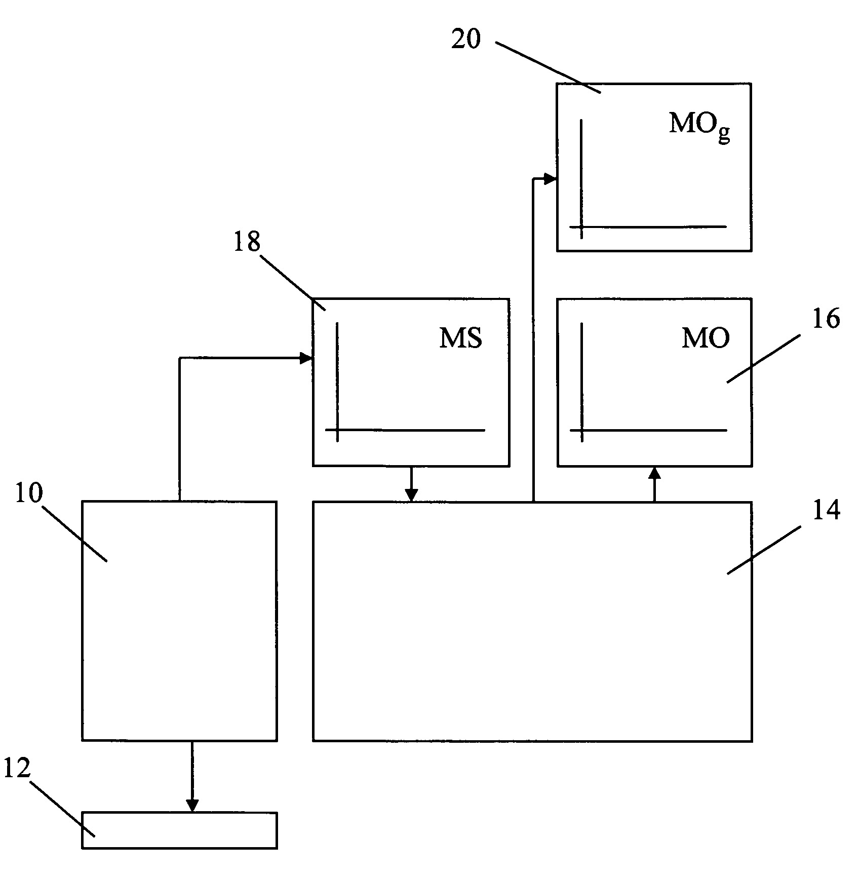
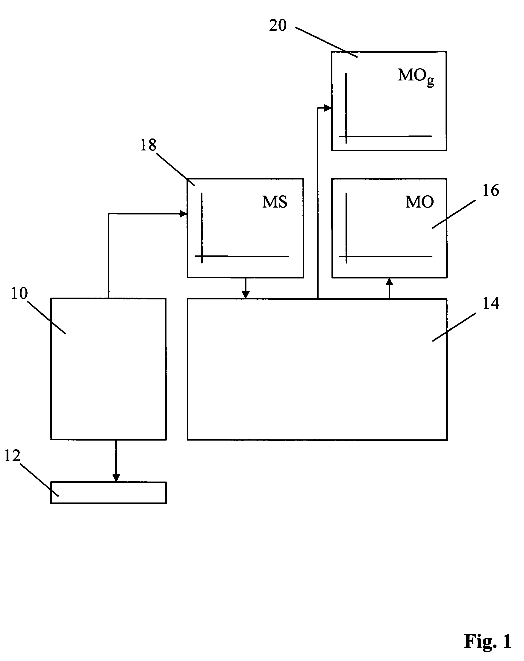
[0029]FIG. 1 schematically shows the structure of the measuring system according to the present invention with the spectra obtained thereby. A measuring or inspection system 10, such as a spectral photometer, is provided with the aid of which a measured spectrum 18 can be recorded from an object 12. The measuring or inspection system can be structured such as described, for example, in DE 101 33 992. Object 12 can be a multilayer system, in particular. The data of the measured spectrum 18 are also made available to a computer unit 14, which can also be integrated into measuring system 10. A model spectrum 16 associated with object 12 and corresponding to measured spectrum 18 is calculated with the aid of a suitable model by computer unit 14.

[0030]In the calculation of model spectra of thick layers, preferably an FFT technique is used, in which any damping, if present, is hardly effective. The determination of the layer thickness is therefore only little influenced by the damping, so...


PUM


Abstract

With technical surfaces, in particular in semiconductor manufacture, it is a regular requirement to obtain the reflection coefficient of an inspected object (12). To better match the calculated model spectrum (16) to the obtained measured spectrum (18) with respect to damping when thick layers are measured, the measuring system (10) is measured with respect to its line spread I(λ). The measured line spread I(λ) is iteratively used for calculating the damping of the model spectrum (16), so that a damped model spectrum (20) is obtained.

Description

CROSS REFERENCE TO RELATED APPLICATIONS[0001]This patent application claims priority of German Patent Application No. 10 2006 003 472.4, filed on Jan. 25, 2006, which application is incorporated herein by reference.FIELD OF THE INVENTION[0002]The invention relates to a method for matching a model spectrum to a measured spectrum of an object, of a multi-layer system.BACKGROUND OF THE INVENTION[0003]With technical surfaces, in particular in semiconductor manufacture, it is often necessary to determine the structural parameters of the surface. During the manufacturing process, applied line widths and line profiles of structured layers must be checked, for example, with respect to their dimensions and uniformity. The exact compliance with specifications for layer thicknesses is critical for the operativeness of the product. To check these manufacturing parameters the reflection on the sample is measured at different wavelengths. These measurements do not directly provide, however, the d...

Claims


Application Information

Patent Timeline
Patent Type & Authority Applications(United States)
IPC IPC(8): G06F19/00
CPCG01B11/24G01B11/0625
Inventor HALM, CHRISTIAN
Owner VISTEC SEMICON SYST JENA
Why Eureka
Try Eureka