Supercharge Your Innovation With Domain-Expert AI Agents!

Self-luminous display apparatus, light emission condition control apparatus, light emission condition control method and program

a display apparatus and light emission condition technology, applied in the direction of electroluminescent light sources, instruments, static indicating devices, etc., can solve the problems of preventing the drop of luminance, and accelerating the drop of the luminance of the display elemen

Active Publication Date: 2007-08-02
JOLED INC
View PDF10 Cites 8 Cited by
  • Summary
  • Abstract
  • Description
  • Claims
  • Application Information

AI Technical Summary

Benefits of technology

[0011] However, the method disclosed in Patent Document 1 prevents a drop of the luminance by adjusting the amount of current with respect to a drop of the luminance of each pixel and merely accelerates dropping of the luminance of the display element. Accordingly, the life of the organic EL panel may not be improved.
[0012] Meanwhile, the method disclosed in Patent Document 2 may not improve the life positively although it can make improvements against the drop of the luminance arising from leak current.
[0013] Also the method disclosed in Patent Document 3 may not improve the life positively although it can make improvements against the drop of the luminance arising from unnecessary light emission time.
[0015] According to an embodiment of the present invention, there is provided a self-luminous display apparatus capable of varying a peak luminance of a display panel in a unit of one frame, including a mean gradation value calculation section configured to calculate a mean gradation value of a video signal in a unit of a frame for each one frame, a specific condition detection section configured to detect, based on the mean gradation values calculated over a period of several frames, an input of the video signal which satisfies a specific condition in which a drop of a physical peak luminance is not likely to be perceived visually, and a light emission condition control section configured to perform dropping control of the peak luminance of the display panel in a unit of a frame so that a dropping condition set in advance may be satisfied for a period of time after the frame which satisfies the specific condition is detected until the detection state is canceled.
[0016] With the self-luminous display apparatus, the peak luminance can be dropped actively while the peak luminance perceived by a visual sense is maintained. As a result, increase of the life of the display panel can be achieved without having an influence on the picture quality of an image displayed on the display panel. Simultaneously, reduction of the power consumption by the display panel can be achieved.

Problems solved by technology

Accordingly, the life of the organic EL panel may not be improved.
Meanwhile, the method disclosed in Patent Document 2 may not improve the life positively although it can make improvements against the drop of the luminance arising from leak current.
Also the method disclosed in Patent Document 3 may not improve the life positively although it can make improvements against the drop of the luminance arising from unnecessary light emission time.

Method used


Image

  • Self-luminous display apparatus, light emission condition control apparatus, light emission condition control method and program
  • Self-luminous display apparatus, light emission condition control apparatus, light emission condition control method and program
  • Self-luminous display apparatus, light emission condition control apparatus, light emission condition control method and program

Examples


example 1

(D-1) Form Example 1

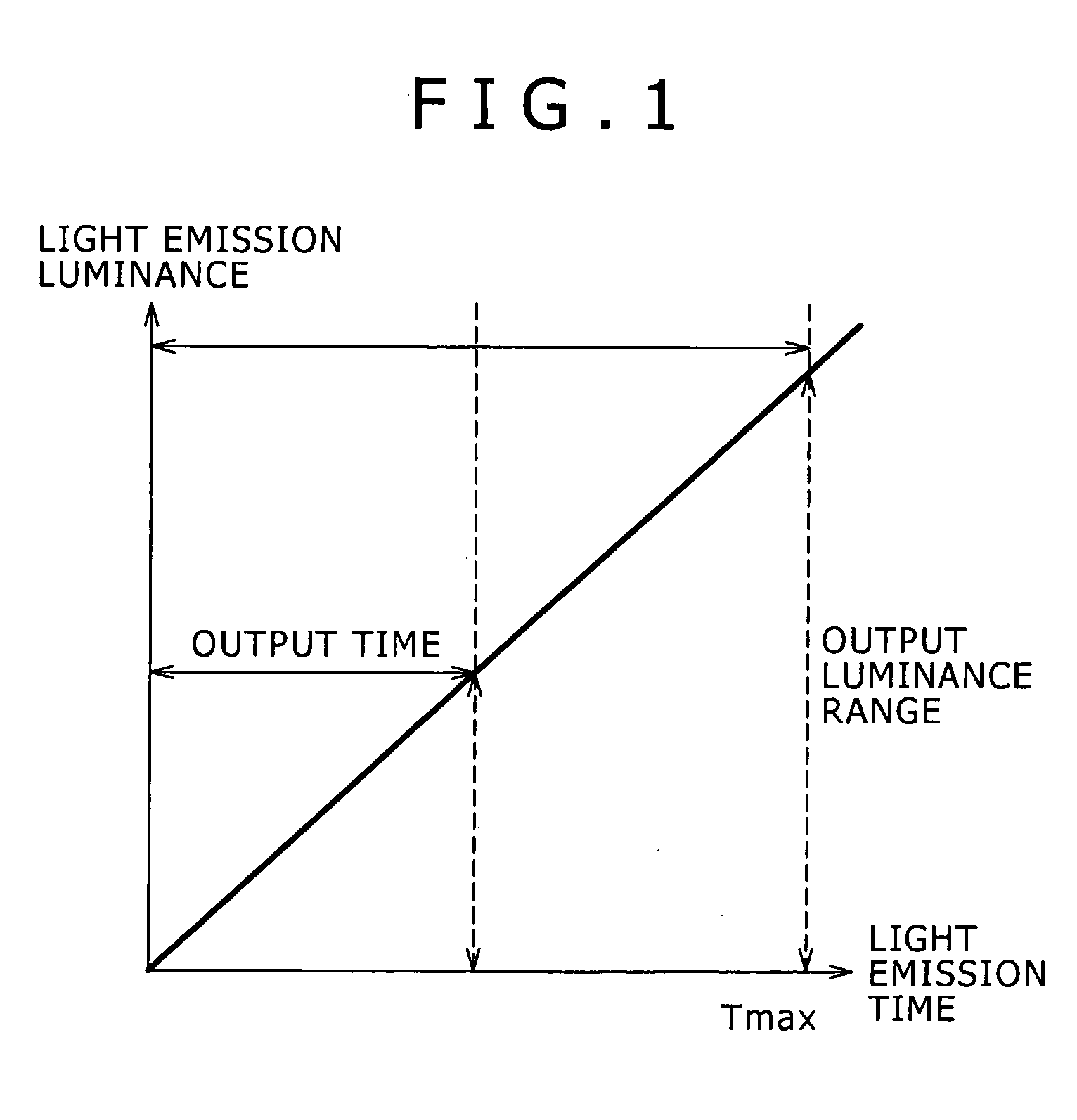
[0075]FIG. 10 shows an example of a configuration of the light emission condition control apparatus 11 suitable for use to perform the dropping control of the peak luminance through control of the light emission time period.

[0076] Referring to FIG. 10, the light emission condition control apparatus 11 includes a mean gradation value calculation section 13, a specific condition detection section 15, a reference duty ratio signal generation section 17 and a duty ratio signal control section 19.

[0077] The mean gradation value calculation section 13 is a processing device for calculating a mean gradation value APLn of a video signal for each one frame. It is to be noted here that the suffix n signifies time such as, for example, a frame number.

[0078] The specific condition detection section 15 is a processing device for detecting, based on a mean value Cn of mean gradation values APLn calculated over several frames, an input of a video signal which satisfies a spe...

example 2

(D-2) Form Example 2

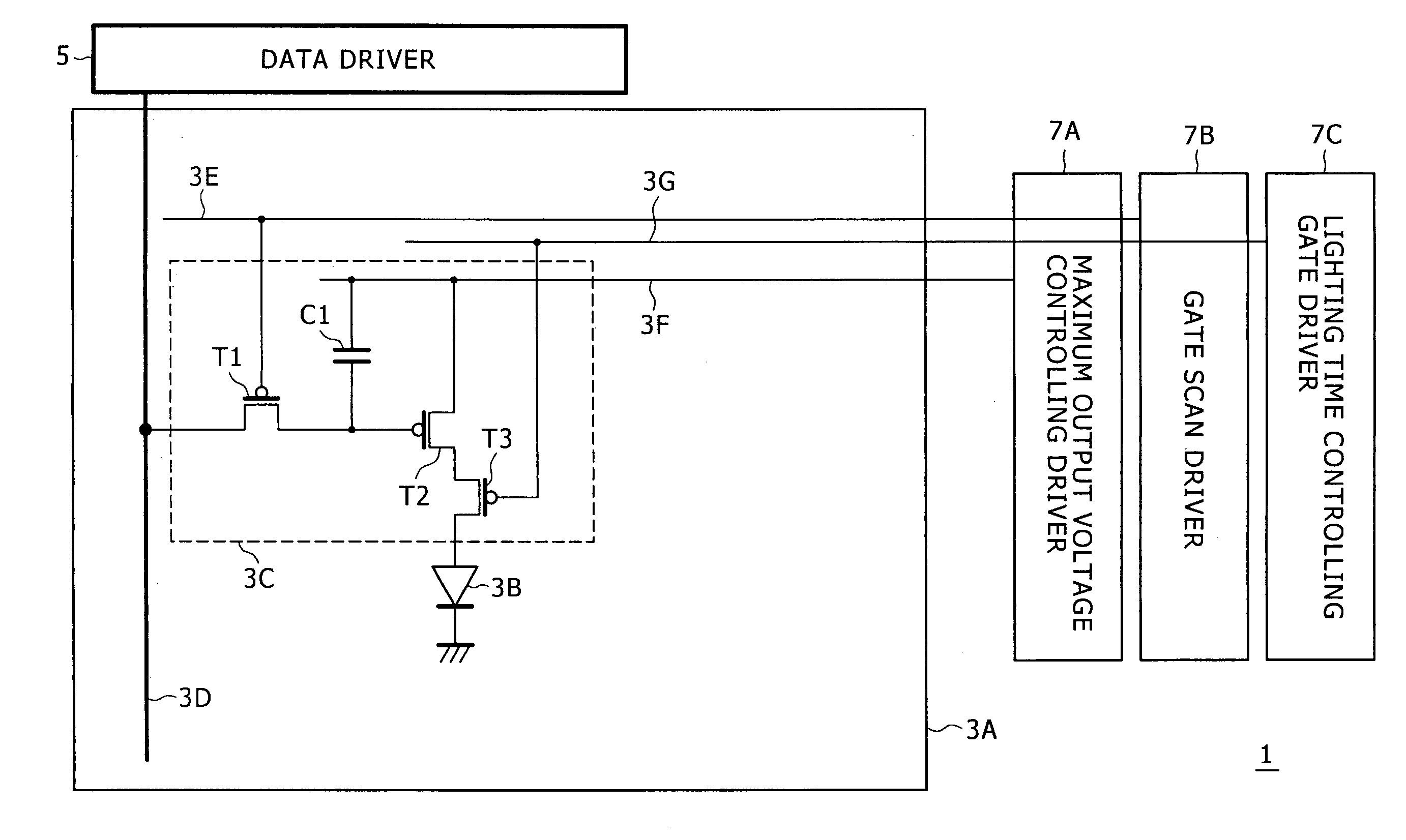
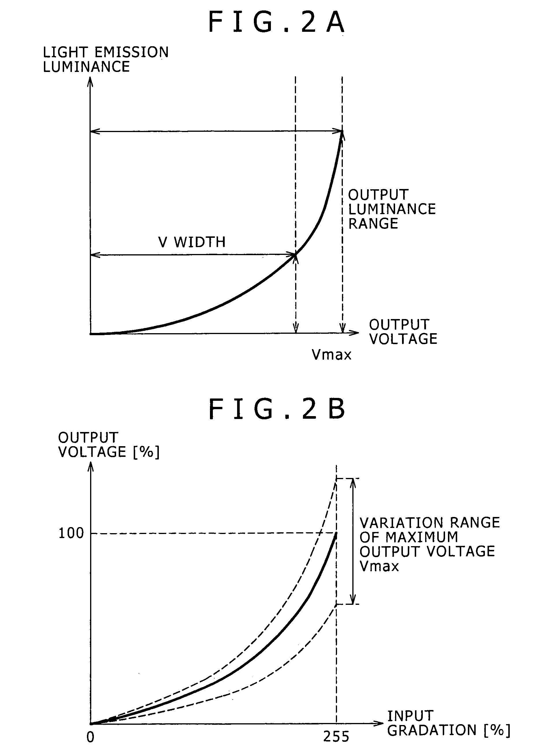
[0097]FIG. 14 shows an example of a configuration of the light emission condition control apparatus 11 suitable for use to perform the dropping control of the maximum output voltage Vmax to be applied to the current supply line 3F.

[0098] Referring to FIG. 14, the light emission condition control apparatus 11 shown includes a mean gradation value calculation section 13, a specific condition detection section 15 and a maximum output voltage control section 21. The mean gradation value calculation section 13 and the specific condition detection section 15 other than the maximum output voltage control section 21 are similar to those in the form example 1 of FIG. 10.

[0099] In particular, the specific condition detection section 15 determines the dropping amount α% for the peak luminance and provides the dropping amount α% to the maximum output voltage control section 21. In the present form example, the maximum output voltage control section 21 functions as a “light...


PUM


Abstract

A self-luminous display apparatus capable of varying a peak luminance of a display panel in a unit of one frame, includes: a mean gradation value calculation section configured to calculate a mean gradation value of a video signal in a unit of a frame for each one frame; a specific condition detection section configured to detect, based on the mean gradation values calculated over a period of several frames, an input of the video signal which satisfies a specific condition in which a drop of a physical peak luminance is not likely to be perceived visually; and a light emission condition control section configured to perform dropping control of the peak luminance in a unit of a frame so that a dropping condition set in advance may be satisfied for a period of time after the frame which satisfies the specific condition is detected until the detection state is canceled.

Description

CROSS REFERENCES TO RELATED APPLICATIONS [0001] The present invention contains subject matter related to Japanese Patent Application JP 2005-340434 filed with the Japanese Patent Office on Nov. 25, 2005, the entire contents of which being incorporated herein by reference. BACKGROUND OF THE INVENTION [0002] 1. Field of the Invention [0003] This invention relates to a self-luminous display apparatus, a light emission condition control apparatus, a light emission condition control method and a program. [0004] 2. Description of the Related Art [0005] An organic EL display apparatus is superior not only in the wide view angle characteristic, high response speed, wide color reproduction range and high contrast but also in that it allows a display panel itself to be formed with a small thickness. Thanks to the advantages mentioned, an organic EL display apparatus draws attention as the most promising candidate for a next-generation flat panel display apparatus. [0006] However, in order to ...

Claims


Application Information

Patent Timeline
IPC IPC(8): G09G3/30H05B44/00
CPCG09G3/2014G09G3/3258G09G2300/0842G09G2300/0861G09G2360/16G09G2320/0271G09G2320/043G09G2320/0626G09G2330/025G09G2320/0233H05B33/14G09G3/30
Inventor TADA, MITSURUOZAWA, ATSUSHI
Owner JOLED INC
Features
  • R&D
  • Intellectual Property
  • Life Sciences
  • Materials
  • Tech Scout
  • Unparalleled Data Quality
  • Higher Quality Content
  • 60% Fewer Hallucinations
Learn More