High-speed capacitor leakage measurement systems and methods

a leakage measurement and high-speed technology, applied in the direction of capacitor testing, resistance/reactance/impedence, digital storage, etc., can solve the problem of wasting time, limiting the number of capacitors to be tested at a time, and unattractive methods for measuring complex systems. problem, to achieve the effect of substantial time saving

Active Publication Date: 2007-08-02
ONTO INNOVATION INC
View PDF8 Cites 17 Cited by
  • Summary
  • Abstract
  • Description
  • Claims
  • Application Information

AI Technical Summary

Benefits of technology

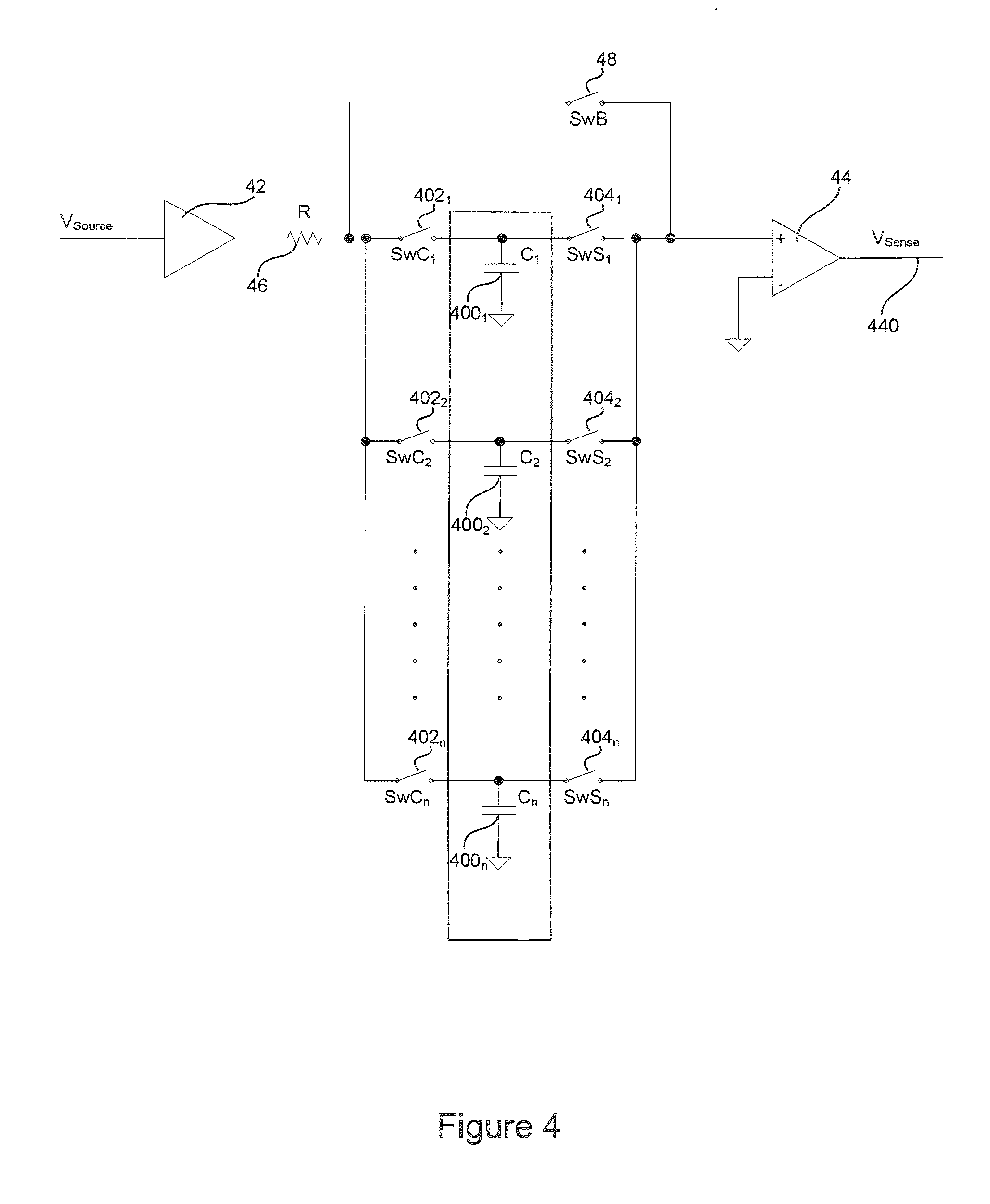
[0010] Certain embodiments of the invention provide systems and methods for measuring capacitor leakage comprising the steps of providing a charging current to a plurality of capacitors, wherein the current charges and soaks the plurality of capacitors. Capacitors can be disconnected from the charging current and their voltage monitored according to a programmed sequence. Monitoring can be periodic in nature. Typically, large numbers of capacitors can be charged and soaked in parallel. The time required for discharge of the capacitors can be monitored sequentially and in parallel, thereby generating substantial time savings in the calculation device of leakage values and parameters.

Problems solved by technology

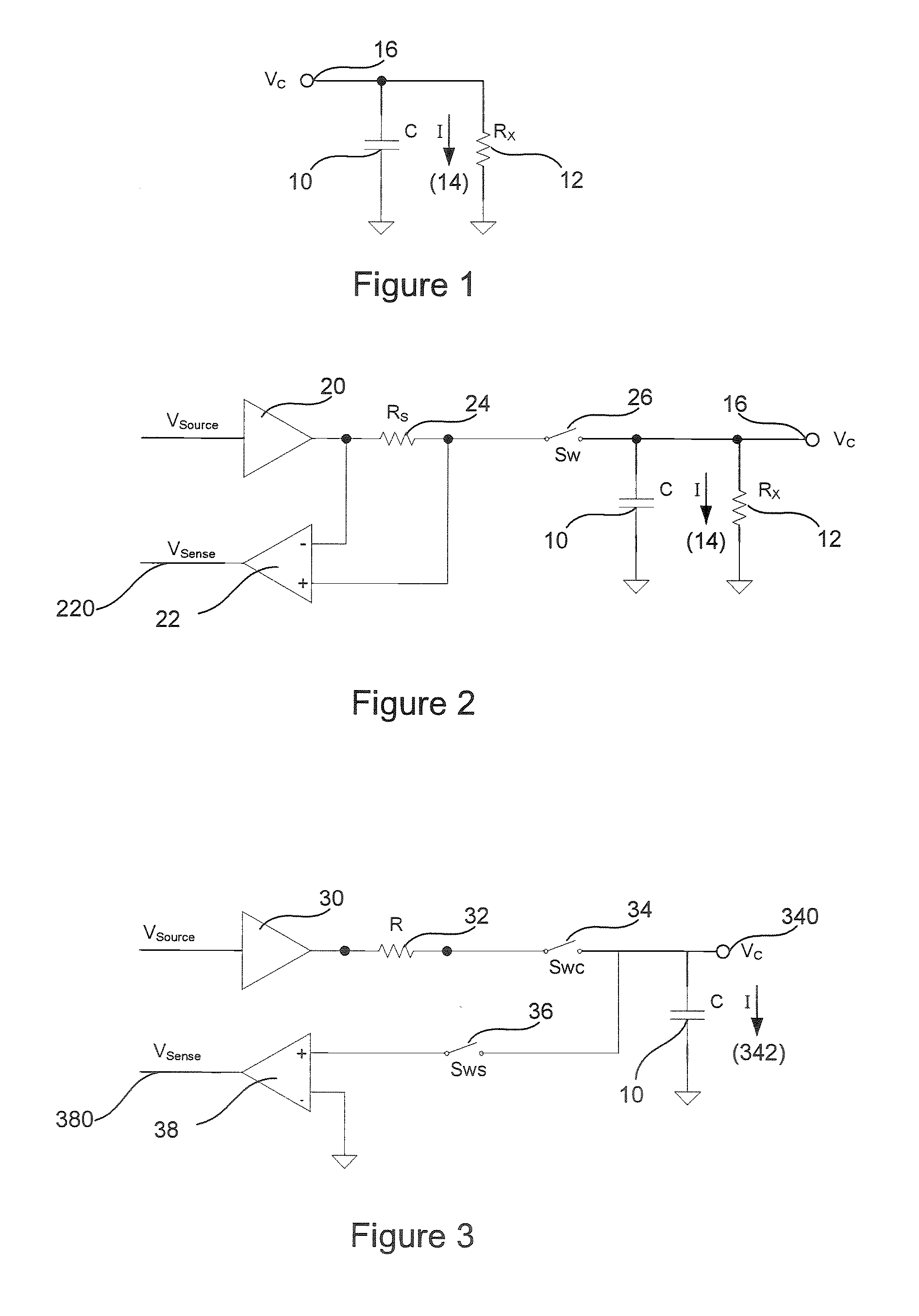
However, certain intrinsic properties of real capacitors cause discharge over time.
Various problems arising from this method to leakage measurement make the method unattractive for measuring complex systems that may contain hundreds or even thousands of large capacitors.
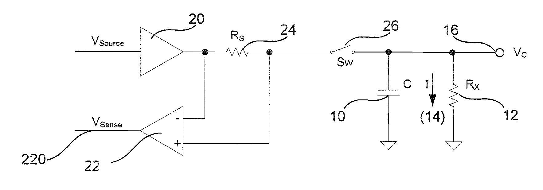
One problem lies with the sense resistor 24.
Another problem with the method of testing is the limitation that only one capacitor can be tested at a time.
For a circuit containing over 100 capacitors, it may take over four hours to obtain accurate leakage currents for the entire circuit.
A manufacturer loses revenue for every minute that the probing process is inoperable, due to a probe card malfunction for example.

Method used


Image

  • High-speed capacitor leakage measurement systems and methods
  • High-speed capacitor leakage measurement systems and methods
  • High-speed capacitor leakage measurement systems and methods

Examples


Embodiment Construction

[0018] Embodiments of the present invention will now be described in detail with reference to the drawings, which are provided as illustrative examples so as to enable those skilled in the art to practice the invention. Notably, the figures and examples below are not meant to limit the scope of the present invention to a single embodiment, but other embodiments are possible by way of interchange of some or all of the described or illustrated elements. Wherever convenient, the same reference numbers will be used throughout the drawings to refer to same or like parts. Where certain elements of these embodiments can be partially or fully implemented using known components, only those portions of such known components that are necessary for an understanding of the present invention will be described, and detailed descriptions of other portions of such known components will be omitted so as not to obscure the invention. In the present specification, an embodiment showing a singular compo...


PUM


Abstract

Systems and methods according to aspects of the present invention are described. The systems and methods enable charging, soaking, and measuring of capacitors to be conducted quickly. Charging and soaking typically occurs in parallel and certain embodiments facilitate the measuring of capacitor leakage by sequentially disconnecting each capacitor and measuring the time for voltage on the capacitor to reach a predetermined threshold. Further, all capacitors can be disconnected from a charging source simultaneously and voltages can be measured for each capacitor simultaneously. Monitoring can be periodic in nature. Substantial time savings in the calculation device of leakage values and parameters can be attained.

Description

CROSS-REFERENCE TO RELATED APPLICATIONS [0001] The present application claims benefit of priority from U.S. Provisional Patent Application Ser. No. 60 / 762,967, titled “System and Method for High-Speed Capacitor Leakage Measurements” and filed Jan. 27, 2006, the contents of which are incorporated herein by reference and for all purposes.BACKGROUND OF THE INVENTION [0002] 1. Field of the Invention [0003] The present invention relates generally to the field of electrical test methods and equipment and more particularly to high-speed electrical testing of capacitors. [0004] 2. Description of Related Art [0005] Rapid testing of capacitor leakage is important in the semiconductor industry. In the semiconductor industry, many replicate components, or die, are created on a single semiconductor wafer. Each of the individual die are electrically tested, commonly with a method called “probing.” During the probing process, a grid array of fine tungsten wires is touched down on the metallized bo...

Claims


Application Information

Patent Timeline
Patent Type & Authority Applications(United States)
IPC IPC(8): G11C11/22
CPCG01R31/028G01R31/27G11C2029/5002G11C29/50016G11C29/50G01R31/64G01R27/26
Inventor CORULLI, CHARLESOLMSTEAD, GREGORYSNOW, DONALD B.
Owner ONTO INNOVATION INC
Why Eureka
Try Eureka