Engine restart apparatus and method

a technology of engine restart and apparatus, which is applied in the direction of engine starters, electric generator control, electric control, etc., to achieve the effect of reducing the aforementioned lag time in the engine starting system

Active Publication Date: 2007-05-15
GM GLOBAL TECH OPERATIONS LLC
View PDF13 Cites 50 Cited by
  • Summary
  • Abstract
  • Description
  • Claims
  • Application Information

AI Technical Summary

Benefits of technology

[0005]Accordingly, the present invention seeks to reduce the aforementioned lag time in the engine starting system for a start-stop “mild hybrid” engine utilizing a conventional engine starter and flywheel as well as providing a method to operate such a system.
[0007]By way of example, when the engine is stopped, the pinion shuttle solenoid is energized to the maximum pull-in current for a predetermined time to allow the pinion gear to shuttle to, and engage the flywheel ring gear. Should the teeth not mesh properly, in a condition referred to as a “butting”, a coil spring is provided behind the pinion gear to hold the pinion gear against the flywheel. The current to the solenoid is then reduced to a “holding level”. This holding level is also predetermined and dependent on the amount of current required to keep the pinion gear meshed with the flywheel ring gear teeth. An alternative method of accomplishing this reduced current “holding” state would be to provide two separate coils in the solenoid and allow one coil circuit to open when the solenoid armature is at full stroke. Concurrent with the pinion gear pre-shuttling operation, the power relay is provided a “prime current”. This “prime current” allows the coil current in the relay to build to a level just below the point at which switching will occur, thereby eliminating much of the time lag inherent when switching a power relay absent a “prime current”. Both the pinion gear and power relay are now in a favorable condition to allow a quick restart of the engine when a restart request is made.
[0009]This invention also provides an improved method of current control for fast response to a restart signal for an engine having a flywheel ring gear and a traditional starter with a pinion gear and having a pinion actuator solenoid and a power relay and a control unit. The method includes: controlling current flow to the pinion actuator solenoid at maximum pull-in current for a predetermined amount of time sufficient to allow the pinion gear to shuttle to the flywheel ring gear, thereafter the pinion actuator solenoid current is decreased to a level to hold the pinion gear in mesh with the flywheel ring gear; and separately controlling current flow to the power relay at less than the minimum pull-in current to allow the relay coil current to ramp to a level that is insufficiently high enough to cause power switching of the power relay, but sufficiently high enough to eliminate a significant portion of the time required for the power relay to be switched in response to the restart signal. In an alternative embodiment of this method, the pinion actuator solenoid may have two coils and an armature actuated set of electrical contacts that are openable to energize the pinion actuator solenoid at a relatively low current level in response to the control unit to control the pinion actuator solenoid.

Problems solved by technology

The time required to energize the traditional power relay switching and the drive gear engagement mechanisms of the starter account for a significant fraction of the total delay time.

Method used


Image

  • Engine restart apparatus and method
  • Engine restart apparatus and method
  • Engine restart apparatus and method

Examples


Embodiment Construction

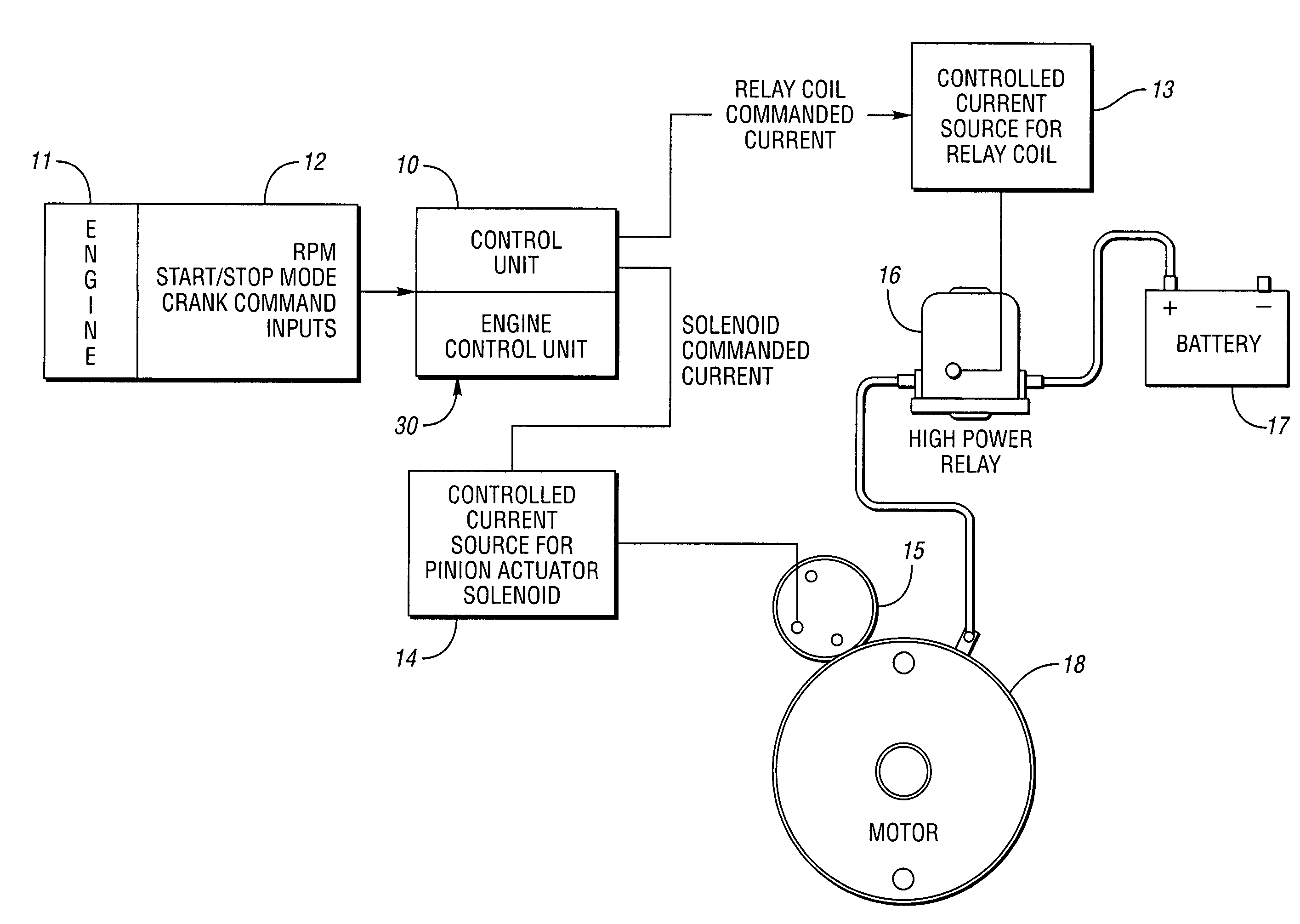
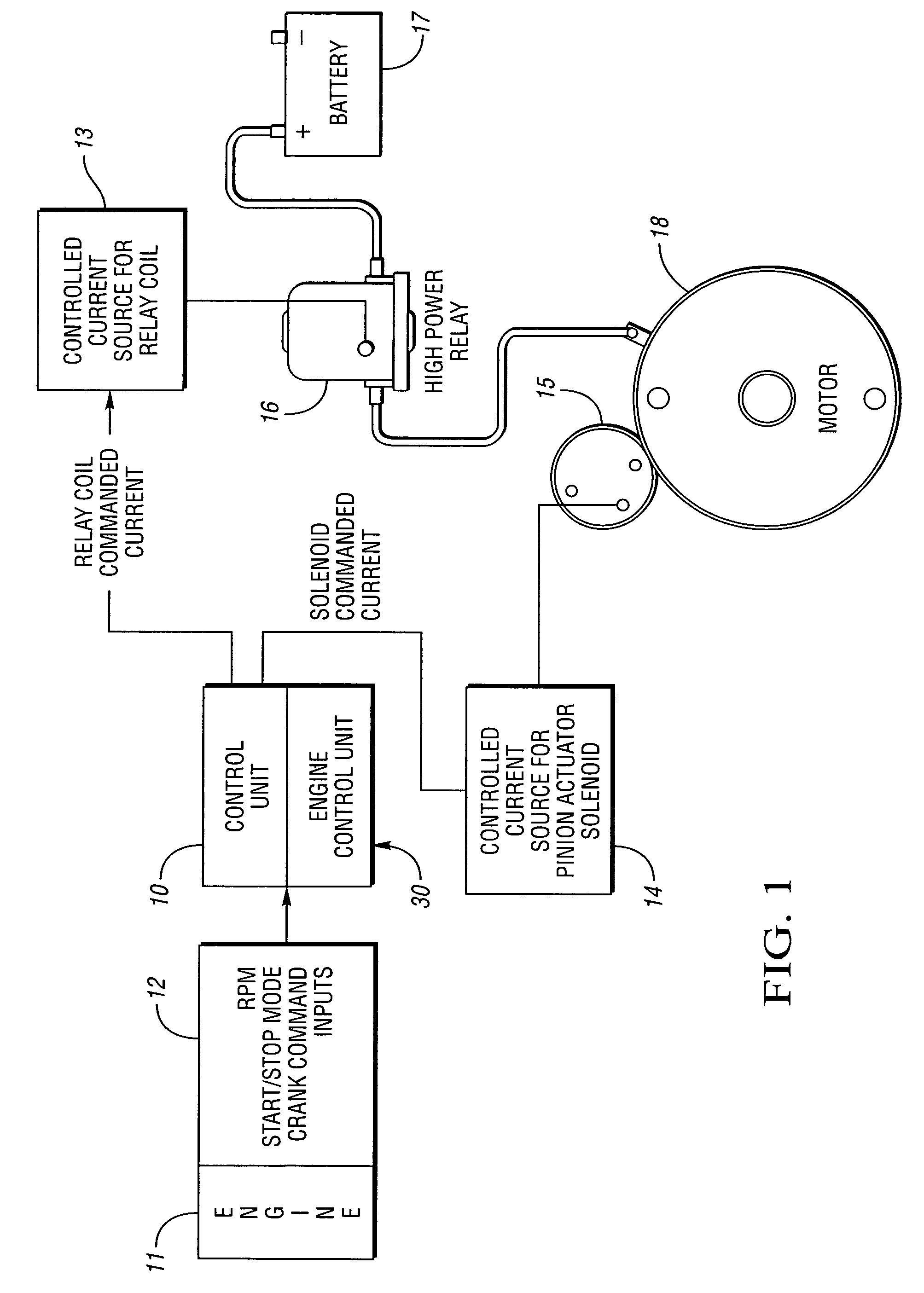
[0017]The present invention is shown schematically in FIG. 1. The engine control unit 30 for engine 11 receives various inputs from the on-vehicle sensors 12 such as engine RPM, start / stop requests, vehicle speed, etc. The cranking control unit 10 may be contained in the engine control unit 30 or may be entirely separate. The inputs 12 are processed by the control unit 10 to determine in what state the engine cranking system should be. The control unit 10 is electrically connected to a power relay controlled current source 13 as well as to a pinion actuator solenoid controlled current source 14. The pinion actuator solenoid controlled current source 14 is connected to the pinion actuator solenoid 15. The power relay controlled current source 13 is connected to a power relay 16. The power relay 16 is connected in series linking the battery 17 and the starter motor 18. The typical voltage for an automotive battery 17 is 12 volts; however, the voltage may be decreased or increased acco...


PUM


Abstract

The present invention relates to a start-stop “mild hybrid” vehicle with a starting system which utilizes traditional engine and transmission architecture. The present invention separates the pinion actuator solenoid from the starter motor power switching circuit. A power relay is provided to switch the starter motor. The pinion gear in the present invention is pre-shuttled to, and held in mesh with, the flywheel ring gear during engine stop conditions. A “prime current” is then applied to the power relay just below that which is required to energize the power relay. Upon request for an engine start, the current will increase to energize the relay and allow the starter motor to spin. A significant amount of time lag is thusly removed from the starting system permitting an expedient restart and launch. The pinion actuator solenoid in this invention may also have two coils which may be selectively energized.

Description

TECHNICAL FIELD[0001]The present invention relates to an apparatus and method to quickly and efficiently restart a start-stop “mild hybrid” internal combustion engine by separating the pinion gear shuttling circuit from the starter motor power relay circuit, pre-shuttling the pinion gear to the flywheel ring gear, and providing the power relay with a “prime current” to reduce the time lag before restart.BACKGROUND OF THE INVENTION[0002]With the current thrust for more fuel efficient and low emission vehicles, many novel solutions for internal combustion engine architectures and operating strategies have been developed. One such strategy is to simply shut off the engine when the engine is operating in an idle mode. Many configurations have been proposed to effect a quick restart of the engine. The simplest and most cost effective systems incorporate a traditional or “off the shelf” starter / pinion gear and flywheel / ring gear configuration. As such, this type of start-stop strategy has...

Claims


Application Information

Patent Timeline
Patent Type & Authority Patents(United States)
IPC IPC(8): F02N11/00H02P9/04F02N99/00
CPCF02N11/0855F02N11/087F02D2041/2044F02N11/0814F02N15/067F02N2200/047F02N2200/065
Inventor ALBERTSON, WILLIAM C.MCDONALD, MIKE M.RIZOULIS, DIMITRIOSBUSLEPP, KENNETH J.VERNER, DOUGLAS R.
Owner GM GLOBAL TECH OPERATIONS LLC
Why Eureka
Try Eureka