
Medical electrical lead having improved inductance

a technology of inductance and medical electrical leads, which is applied in the direction of internal electrodes, transvascular endocardial electrodes, therapy, etc., can solve the problems of multifilarity and low inductance of cables

Active Publication Date: 2007-08-02
MEDTRONIC INC
View PDF51 Cites 118 Cited by
  • Summary
  • Abstract
  • Description
  • Claims
  • Application Information

AI Technical Summary

Benefits of technology

[0004] The present invention comprises a strength-enhanced conductor for a medical electrical lead. The conductor connects an electrode near a distal end of a medical electrical lead with an implantable medical dev...

Problems solved by technology

These multi-filar, cables, however, have very low inductance particularly due to the straight central filar.

Method used


Image

  • Medical electrical lead having improved inductance
  • Medical electrical lead having improved inductance
  • Medical electrical lead having improved inductance

Examples


Embodiment Construction

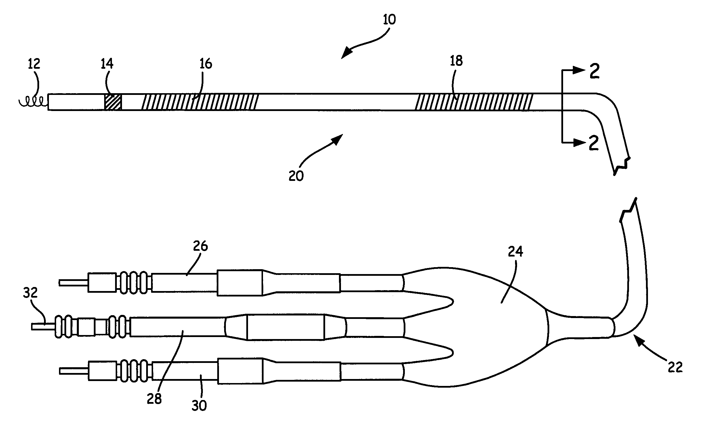
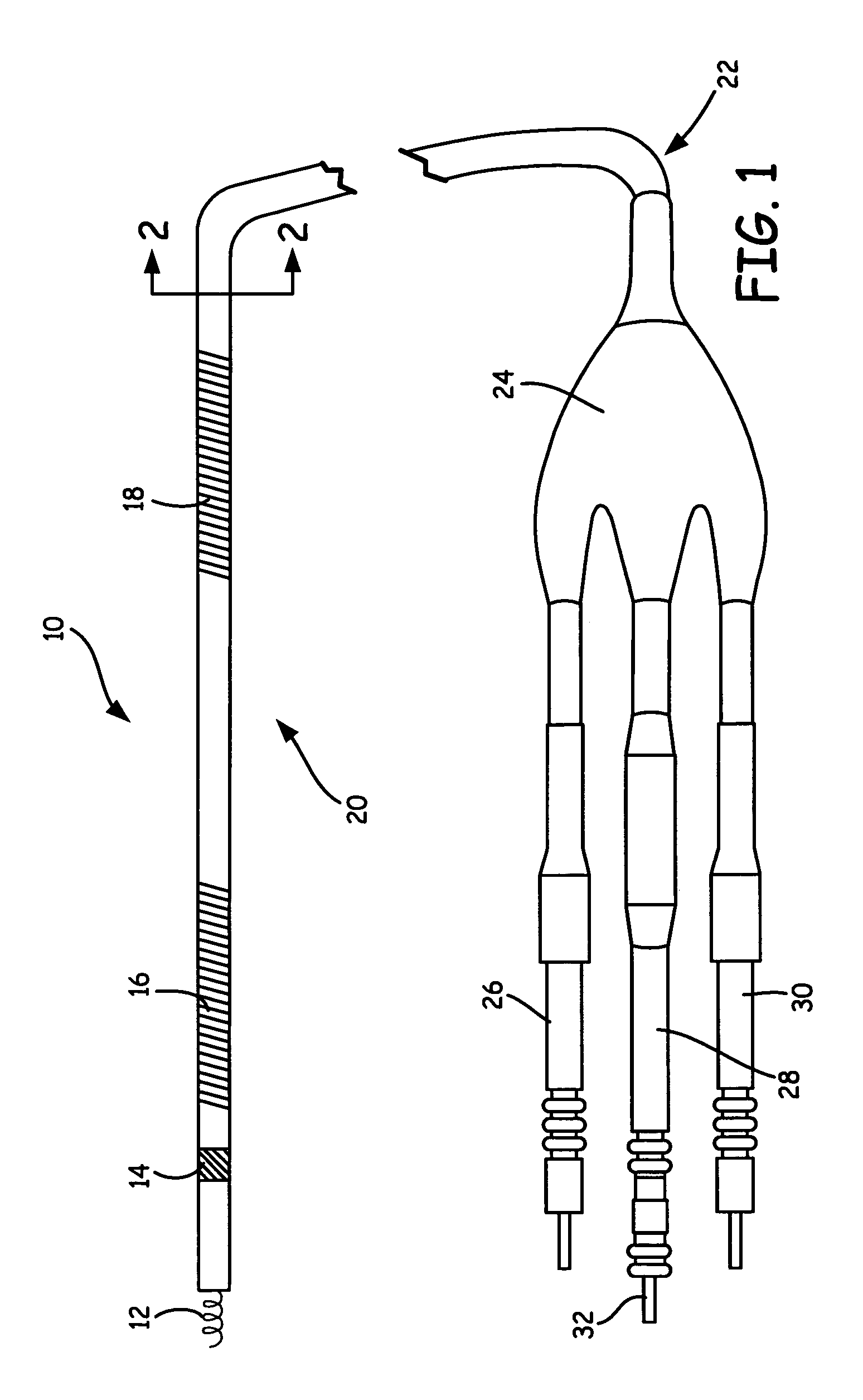
[0009]FIG. 1 shows implantable cardioverter defibrillation (ICD) lead 10 of the present invention. ICD lead 10 is used to deliver tip electrode 12, ring electrode 14, right ventricle (RV) defibrillation coil 16 and superior vena cava (SVC) defibrillation coil 18 to a heart for the purposes of providing cardio-therapy.

[0010] Tip electrode 12, ring electrode 14, RV coil 16 and SVC coil 18 are connected at distal end 20 of ICD lead 10 with various conductors that run to proximal end 22 of ICD lead 10, where the conductors are joined with connector assembly 24. Connector assembly 24 routes the individual conductors to connectors 26, 28 and 30 for connection with connector sockets of an implantable medical device (IMD).

[0011] Tip electrode 12 and ring electrode 14 are connected with connector 28 and with a conductor coil and a conductor cable, respectively, which are electrically isolated within lead 10. Tip electrode 12 and ring electrode 14 are used to sense cardiac signals and to de...


PUM


Abstract

A conductor for connecting an electrode near a distal end of a medical electrical lead with an implantable medical device connected with a proximal end of the medical electrical lead includes a multi-filar coil wrapped around a central core. The multi-filar coil has an inductance of approximately 0.5 μH or greater, and the central core is non-conducting and provides reinforcement for the multi-filar coil.

Description

CROSS REFERENCE TO RELATED APPLICATION(S) [0001] The following co-pending application is filed on the same day as this application: “POLYMER REINFORCED COIL CONDUCTOR FOR TORQUE TRANSMISSION” by inventors M. T. Marshall and H. D. Schroder (attorney docket number P21933), and is incorporated herein by reference. BACKGROUND OF THE INVENTION [0002] The present invention relates generally to implantable medical device (IMD) leads for delivering active electrodes to various places in a human body, such as the heart. In particular, the present invention relates to lead conductors that are compatible with radio frequency (RF) fields generated by magnetic resonance imaging (MRI). [0003] Typical leads for use with an IMD, such as an implantable cardioverter defibrillation (ICD) device, deliver multiple conductors to the heart for performing pacing, cardioverting, defibrillating, sensing and monitoring functions. One or more of these conductors typically comprises a multi-filar cable in which...

Claims


Application Information

Patent Timeline
IPC IPC(8): A61N1/00
CPCA61N1/08A61N1/056A61N1/3718
Inventor MARSHALL, MARK T.SEIFERT, KEVIN R.
Owner MEDTRONIC INC
Features
  • Generate Ideas
  • Intellectual Property
  • Life Sciences
  • Materials
  • Tech Scout
  • Unparalleled Data Quality
  • Higher Quality Content
  • 60% Fewer Hallucinations
Learn More