Faucet or valve handle turning tool

a faucet handle and handle technology, applied in the field of plumbing tools, can solve the problems of affecting the operation damage to the handle, and difficulty in accessing the valve and obtaining the leverage, so as to reduce the possibility of damage to the handle surface of the faucet handle, and reduce the possibility of damage to the handle surfa

Inactive Publication Date: 2007-08-09
RHODA THOMAS J
View PDF8 Cites 5 Cited by
  • Summary
  • Abstract
  • Description
  • Claims
  • Application Information

AI Technical Summary

Benefits of technology

[0003] The faucet or valve handle turning tool of the present invention facilitates alternative rotation of a faucet or valve handle, and in particular, faucet or valve handles located in cramped working quarters. In addition, the invention provides a recessed gripping cavity of relatively soft material when compared with the exposed gripping surface of said tool handle. The recessed gripping cavity of the tool may be relatively straight in configuration including a major and a minor axis to provide increased rotational strength required for rotation of said tool handle upon a faucet or valve handle.
[0010] It is a further object of this invention to provide a faucet or valve handle turning tool including one end of the tool terminating in a recess or cavity of lesser material hardness when compared to the hardness of the exposed surface of the faucet or valve handle, to thereby reduce the possibility of damage to a gripped faucet handle surface.

Problems solved by technology

Because a significant amount of time can elapse between actuation of the shut off faucet or valve, it is common for these valves to “stick” or become difficult to operate.
In addition, the location of the shut off faucet or valve in close proximity to the plumbing fixture often makes it difficult easily access the valve and obtain the needed leverage to turn the valve handle to the off position.
Furthermore, placing a common monkey wrench, pipe wrench or channel lock pliers on the faucet or valve handle can damage (and sometimes destroy) the handle.

Method used


Image

  • Faucet or valve handle turning tool
  • Faucet or valve handle turning tool
  • Faucet or valve handle turning tool

Examples


Embodiment Construction

[0022] Although the disclosure hereof is detailed and exact to enable those skilled in the art to practice the invention, the physical embodiments herein disclosed merely exemplify the invention that may be embodied in other specific structures.

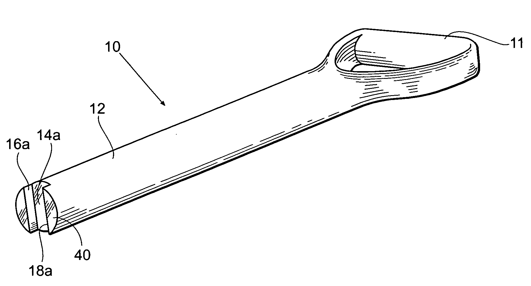
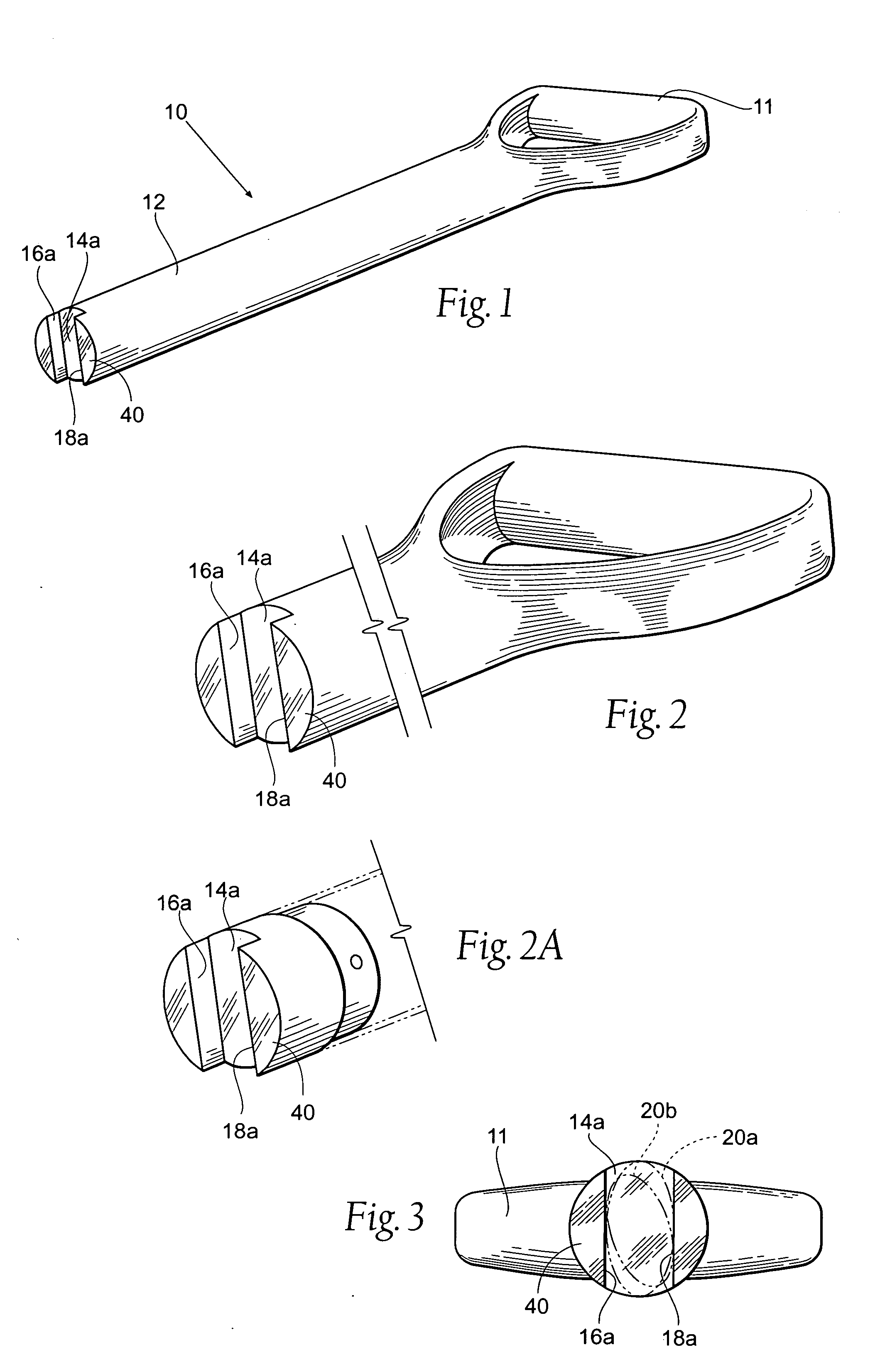
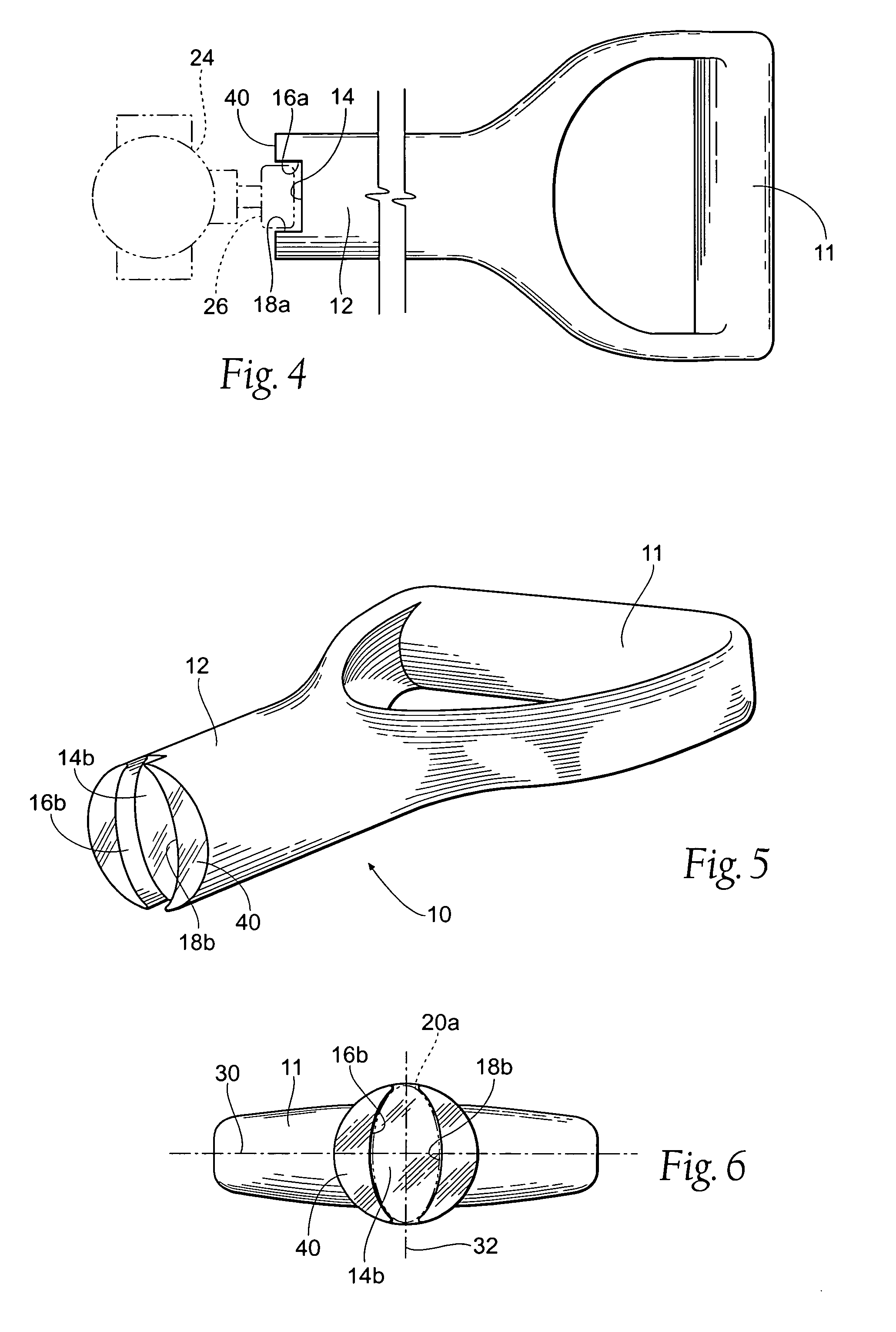
[0023] Referring to the drawings, there is illustrated the tool 10 of this invention having a generally cylindrical, elongated, body 12 with a radially extended lever arm or handle 11 and distal end 40. The lever arm 11 extends from the periphery of the cylindrical body 12 to provide manually rotatable leverage to the tool for rotation of a valve handle (not shown in FIG. 1). In the present case, it has been found to be convenient to form the lever arm 11 in the shape of a conventional “shovel-type” handle which may be formed as an integral part of the body 12, as shown. A preformed handle (not shown) may be made of two mating elongate members affixed or otherwise joined in mating relationship to surround the cylindrical body 12. In addition...


PUM


Abstract

A faucet or valve handle turning tool is provided and includes an elongated, cylindrical body of machinable or moldable material having a handle at one end and a cavity formed in the opposite end. The cavity is formed with inwardly extending sidewalls and has at least one portion conforming to the peripheral contour of a faucet or valve handle. In particular, the sidewalls of such cavity may have similar elliptical contours. In at least one example, the cavity may be formed by means of mechanical routing and removal of material from the tool body. In use, the tool thereby reduces the possibility of damage to a polished faucet or valve handle frequently caused by hardened conventional plumbing tools.

Description

BACKGROUND OF THE INVENTION [0001] The present invention relates generally to a plumbing tool and, more specifically, to a versatile faucet or valve handle turning tool. When servicing or replacing plumbing fixtures, such as sinks and toilets, it is often required that the water supply to the fixture be turned off. It is typical in residential and commercial construction to place a shut off faucet or valve in close proximity to the plumbing fixture. Because a significant amount of time can elapse between actuation of the shut off faucet or valve, it is common for these valves to “stick” or become difficult to operate. In addition, the location of the shut off faucet or valve in close proximity to the plumbing fixture often makes it difficult easily access the valve and obtain the needed leverage to turn the valve handle to the off position. Furthermore, placing a common monkey wrench, pipe wrench or channel lock pliers on the faucet or valve handle can damage (and sometimes destroy)...

Claims


Application Information

Patent Timeline
Patent Type & Authority Applications(United States)
IPC IPC(8): A47K17/00
CPCB25B13/50B25B13/48
Inventor RHODA, THOMAS J.
Owner RHODA THOMAS J
Why Eureka
Try Eureka