Pulse detonation combustor with folded flow path

a combustor and pulse technology, applied in the direction of combustion types, turbine/propulsion engine ignition, turbine/propulsion fuel heating, etc., can solve the problems of high cost and ineffective generation of thrus

Inactive Publication Date: 2007-08-09
GENERAL ELECTRIC CO
View PDF2 Cites 79 Cited by
  • Summary
  • Abstract
  • Description
  • Claims
  • Application Information

AI Technical Summary

Problems solved by technology

However, the thrust may not be effective...

Method used


Image

  • Pulse detonation combustor with folded flow path
  • Pulse detonation combustor with folded flow path
  • Pulse detonation combustor with folded flow path

Examples


Embodiment Construction

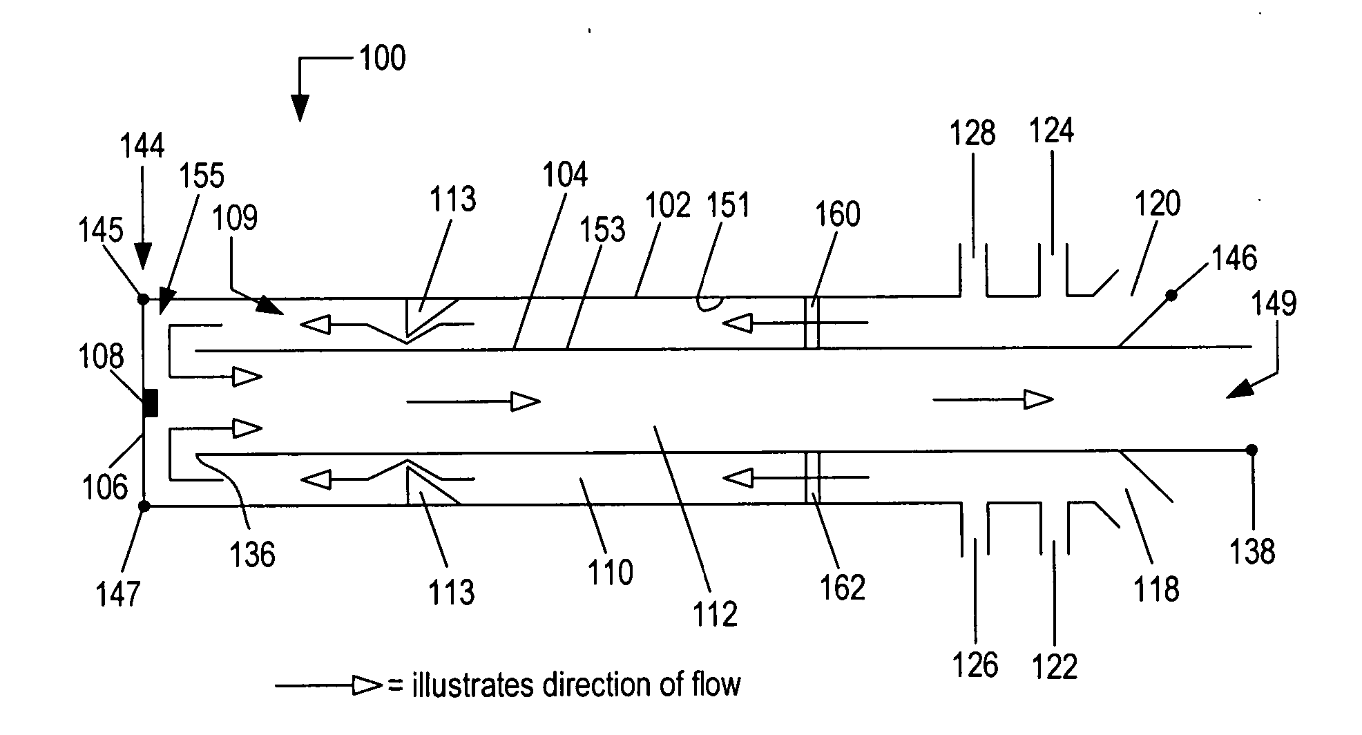
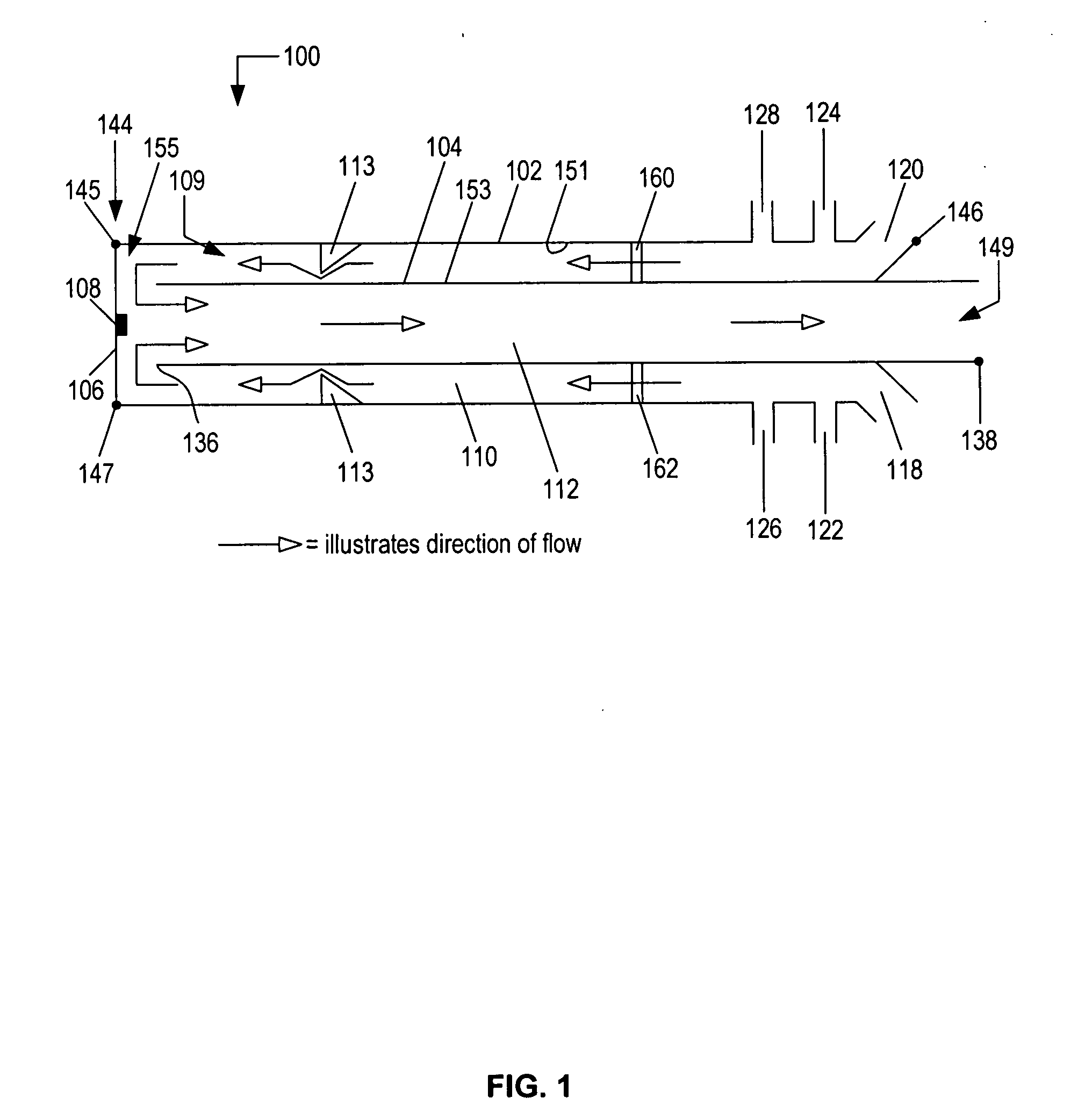
[0015] As used herein, a “pulse detonation combustor” (PDC) includes a device or system that produces both a pressure rise and velocity increase from a single, or a series of repeating, detonations or quasi-detonations within the device. A “quasi-detonation” is a supersonic turbulent combustion process that produces a pressure rise and velocity increase higher than a pressure rise and velocity increase produced by a sub-sonic deflagration wave. Embodiments of PDCs include a device that ignites a fuel / oxidizer mixture, such as, for example, a fuel / air mixture, and a detonation chamber, in which pressure wave fronts initiated by an ignition coalesce to produce a detonation wave. Each detonation or quasi-detonation is initiated either by an external ignition, such as spark discharge or laser pulse, or by gas dynamic processes, such as shock focusing, autoignition or by another detonation (cross-fire). A geometry of a detonation chamber is such that the pressure rise of the detonation w...


PUM


Abstract

A pulsed detonation combustor (PDC) is described. The PDC includes an outer casing defining a first hollow chamber configured to receive a flow and an inner liner. The inner liner includes at least one portion positioned within the first hollow chamber and configured to receive the flow from a plenum formed between the outer casing and inner liner. The PDC further includes a flow turning device with geometric features configured to direct the flow from the plenum to a second hollow chamber defined within the inner liner. The PDC also includes at least one fuel injection port located downstream of an inlet to the outer casing and an ignition device located downstream of the at least one fuel injection port and configured to periodically ignite fuel.

Description

BACKGROUND OF THE INVENTION [0001] The present invention generally relates to cyclic pulsed detonation combustors (PDCs) and more particularly to a design that incorporates a “folded” flow path in order to cool the PDC using an oxidizer and / or fuel prior to a combustion process and, which utilizes heat produced in the combustion process to preheat and mix fuel and / or oxidizer and vaporize fuel prior to initiation. [0002] A typical pulse detonation combustion system generates a thrust upon igniting a mixture of fuel and air within the system. However, the thrust may not be effectively generated and may be expensive to generate. BRIEF DESCRIPTION OF THE INVENTION [0003] In one aspect, A pulsed detonation combustor (PDC) is described. The PDC includes an outer casing defining a first hollow chamber configured to receive a flow and an inner liner. The inner liner includes at least one portion positioned within the first hollow chamber and configured to receive the flow from a plenum for...

Claims


Application Information

Patent Timeline
IPC IPC(8): F02C5/00
CPCF01D25/12F02C5/00F23R7/00F23C15/00F02C7/224
Inventor CHAPIN, DAVID MICHAELHINCKLEY, KEVIN MICHAELTANGIRALA, VENKAT ESWARLUDEAN, ANTHONY JOHN
Owner GENERAL ELECTRIC CO
Why Eureka
Try Eureka