
Polycrystalline diamond abrasive elements

a technology of abrasives and diamonds, applied in the field of polycrystalline diamond abrasives, can solve the problems of increasing the damage to the table, prone to fracture, and becoming more brittle or prone to fracture, and pcd elements designed for improving wear performance will therefore tend to compromise or reduce the resistance to spalling

Active Publication Date: 2007-08-09
BAKER HUGHES INC
View PDF41 Cites 165 Cited by
  • Summary
  • Abstract
  • Description
  • Claims
  • Application Information

AI Technical Summary

Benefits of technology

[0014] The polycrystalline diamond table may be in the form of a single layer, which has a high wear resistance. This may be achieved, and is preferably achieved, by producing the polycrystalline diamond from a mass of diamond particles having at least three, and preferably at least five different particle sizes. The diamond particles in this mix of diamond particles are preferably fine.
[0029] It has been found that the PCD abrasive elements of the invention have a wear resistance, impact strength and hence cutter life comparable to that of PCD abrasive elements of the prior art, whilst requiring only roughly 20% of the treatment time required by the prior art PCD abrasive elements for removing catalysing material from the PCD layer.

Problems solved by technology

However, as PCD material is made more wear resistant it typically becomes more brittle or prone to fracture.
PCD elements designed for improved wear performance will therefore tend to have compromised or reduced resistance to spalling.
Once chipping begins, the amount of damage to the table continually increases, as a result of the increased normal force now required to achieve the required depth of cut.
Therefore, as cutter damage occurs and the rate of penetration of the drill bit decreases, the response of increasing weight on bit can quickly lead to further degradation and ultimately catastrophic failure of the chipped cutting element.
Removal of the metallic phase can be very difficult to control and may result in damage to the highly vulnerable interface region between the PCD layer and the underlying carbide substrate.
In addition, in many cases the substrate is more vulnerable to acid attack than the PCD table itself, and acid damage to the metallic phase in this component will render the cutter useless or highly compromised in the application.
Masking technologies are employed to protect the majority of the PCD table (where leaching is not required) and the carbide substrate, but these are not always successful, especially under extended periods of treatment.
The highly dense nature of the PCD typically treated requires extreme treatment conditions and / or time periods to achieve this depth of leach.
In many cases the masking technologies available do not provide sufficient protection damage on all units undergoing the treatment.

Method used


Image

  • Polycrystalline diamond abrasive elements
  • Polycrystalline diamond abrasive elements
  • Polycrystalline diamond abrasive elements

Examples


first embodiment

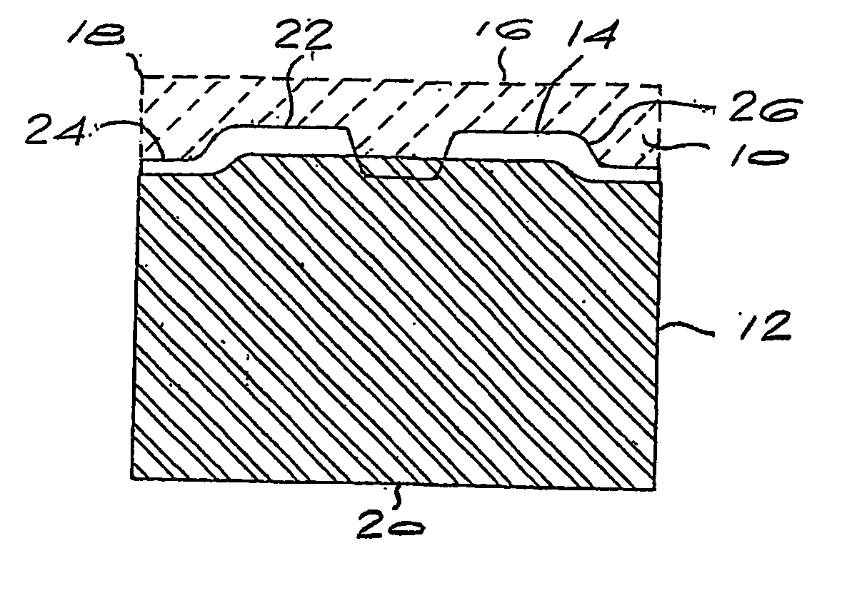
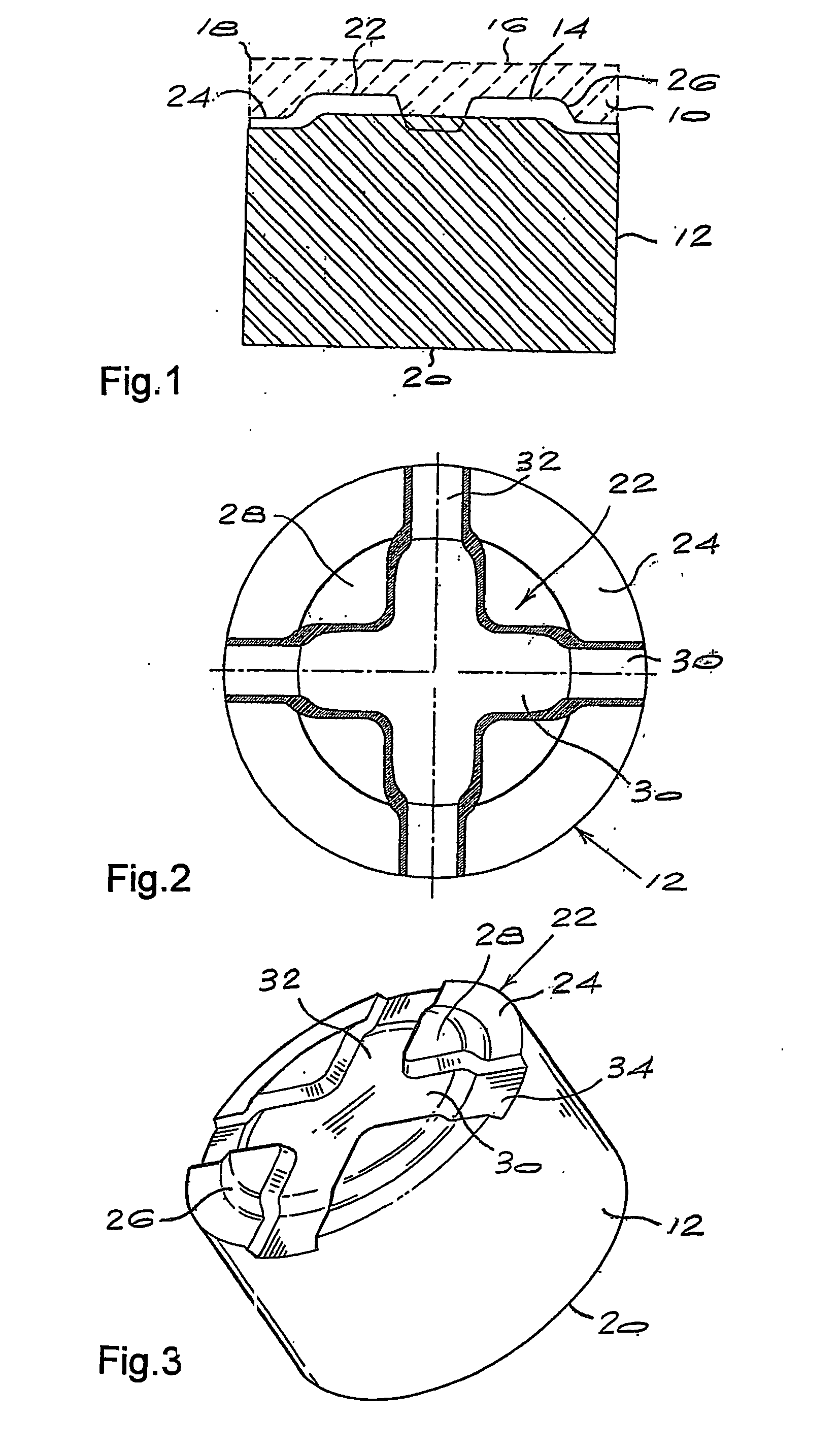
[0041]FIGS. 2 and 3 illustrate more clearly the cemented carbide substrate used in the invention shown in FIG. 1. The substrate 12 has a flat bottom surface 20 and a profiled upper surface 22, which generally has a cruciform configuration. The profiled upper surface 22 has the following features: [0042] i. A stepped peripheral region defining a ring 24. The ring 24 has a sloping surface 26 which connects an upper flat surface or region 28 of the profiled surface 22. [0043] ii. Two intersecting grooves 30, 32, which define a cruciform recess, that extend from one side of the substrate to the opposite side of the substrate. These grooves are cut through the upper surface 28 and also through the base surface 34 of the ring 24.

second embodiment

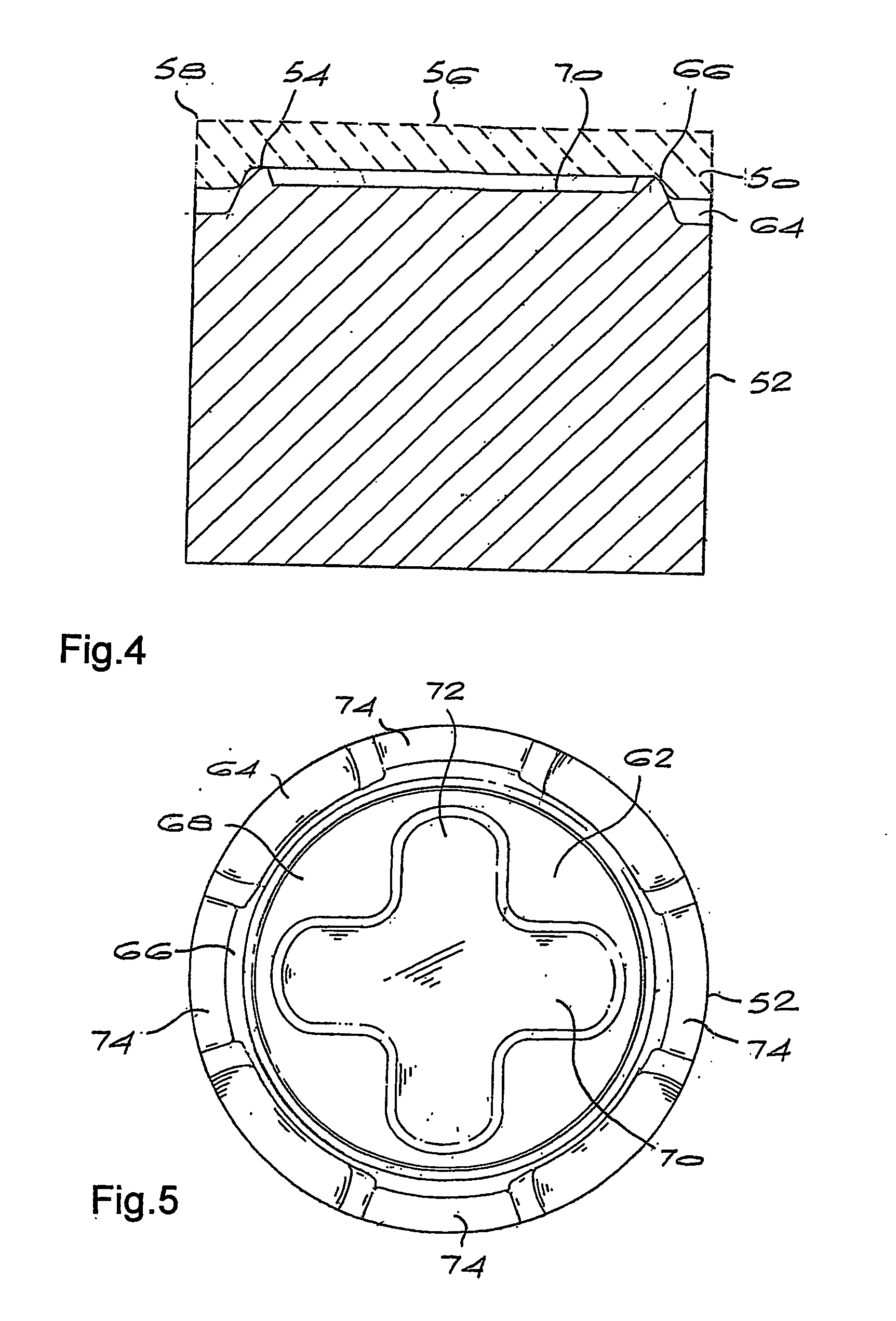
[0044] Referring now to FIG. 4, a polycrystalline diamond abrasive element of the invention comprises a layer 50 of polycrystalline diamond (shown in phantom lines) bonded to a cemented carbide substrate 52 along an interface 54. The polycrystalline diamond layer 50 has an upper working surface 56, which has a cutting edge 58. The edge is illustrated as being a sharp edge. This edge can also be bevelled. The cutting edge 58 extends around the entire periphery of the surface 56.

[0045]FIGS. 5 and 6 illustrate more clearly the cemented carbide substrate used in the second embodiment of the invention, as shown in FIG. 4. The substrate 52 has a flat bottom surface 60 and a profiled upper surface 62. The profiled upper surface 62 has the following features: [0046] i. A stepped peripheral region defining a ring 64. The ring 64 has a sloping surface 66 which connects an upper flat surface or region 68 of the profiled surface. [0047] ii. Two intersecting grooves 70, 72 forming a cruciform fo...


PUM

PropertyMeasurementUnit
depthaaaaaaaaaa
particle sizeaaaaaaaaaa

Abstract

A polycrystalline diamond abrasive element, particularly a cutting element, comprises a table of polycrystalline diamond bonded to a substrate, particularly a cemented carbide substrate, along a non-planar interface. The non-planar interface typically has a cruciform configuration. The polycrystalline diamond has a high wear-resistance, and has a region adjacent the working surface lean in catalysing material and a region rich in catalysing material. The region lean in catalysing material extends to a depth of 40 to 90 microns, which is much shallower than in the prior art. Notwithstanding the shallow region lean in catalysing material, the polycrystalline diamond cutters have a wear resistance, impact strength and cutter life comparable to that of prior art cutter, but requiring only 20% of the treatment times of the prior art cutters.

Description

BACKGROUND OF THE INVENTION [0001] This invention relates to polycrystalline diamond abrasive elements. [0002] Polycrystalline diamond abrasive elements, also known as polycrystalline diamond compacts (PDC), comprise a layer of polycrystalline diamond (PCD) generally bonded to a cemented carbide substrate. Such abrasive elements are used in a wide variety of drilling, wear, cutting, drawing and other such applications. PCD abrasive elements are used, in particular, as cutting inserts or elements in drill bits. [0003] Polycrystalline diamond is extremely hard and provides an excellent wear-resistant material. Generally, the wear resistance of the polycrystalline diamond increases with the packing density of the diamond particles and the degree of inter-particle bonding. Wear resistance will also increase with structural homogeneity and a reduction in average diamond grain size. This increase in wear resistance is desirable in order to achieve better cutter life. However, as PCD mater...

Claims


Application Information

Patent Timeline
Patent Type & Authority Applications(United States)
IPC IPC(8): E21B10/62B24D18/00B24D99/00E21B10/56E21B10/573
CPCB24D18/00B24D99/005E21B10/5735Y10T408/81E21B10/46E21B10/567C22C26/00
Inventor LANCASTER, BRETTROBERTS, BRONWYN ANNETTEPARKER, IMRAANTANK, KLAUSACHILLES, ROY DERRICKVAN DER RIET, CLEMENT DAVID
Owner BAKER HUGHES INC
Learn More