Sunroof apparatus

a technology of sunroof and rack belt, which is applied in the direction of roofs, mechanical devices, transportation and packaging, etc., can solve the problems of bending the rack belt depending on the angle of the roof surfa

Inactive Publication Date: 2007-08-09
AISIN SEIKI KK
View PDF8 Cites 22 Cited by
  • Summary
  • Abstract
  • Description
  • Claims
  • Application Information

AI Technical Summary

Problems solved by technology

However, because of such wire serving as a reinforcement member, it may be diffic

Method used


Image

  • Sunroof apparatus
  • Sunroof apparatus
  • Sunroof apparatus

Examples


first embodiment

[0020]a sunroof apparatus 10 related to the present invention will be explained in accordance with the attached drawings.

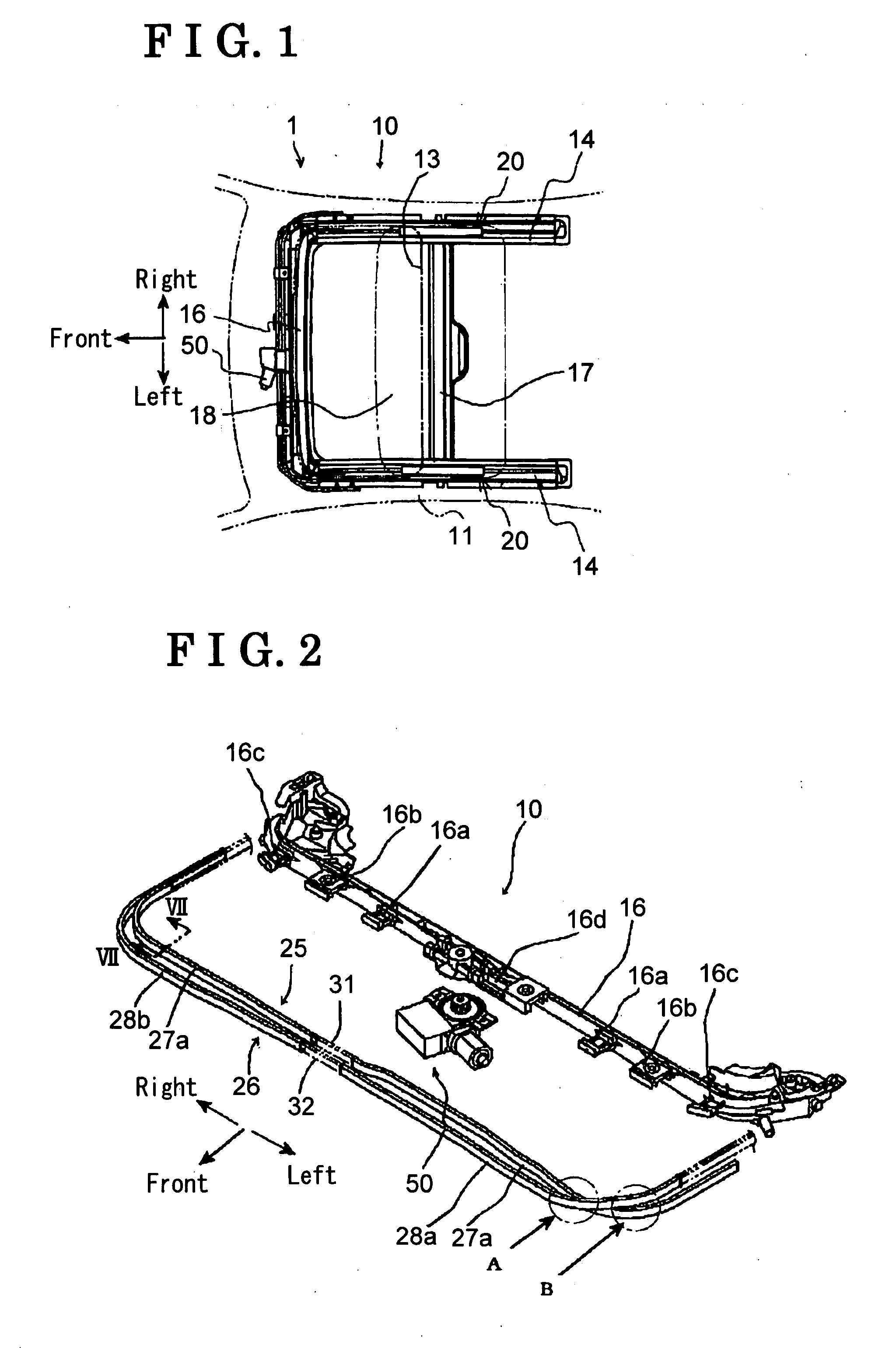
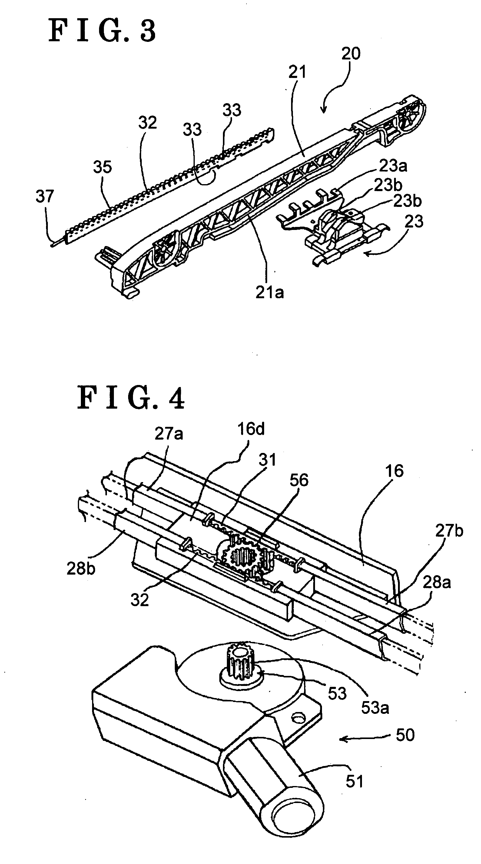
[0021]FIG. 1 illustrates a top view indicating the sunroof apparatus 10 attached to a roof 11 of a vehicle 1. FIG. 2 illustrates an exploded perspective view indicating a front portion of the sunroof apparatus 10.

[0022]Each direction indicated by arrows in the drawings represents a front direction, a left direction and a right direction relative to the vehicle 1. Because the sunroof apparatus 10 basically has a symmetric structure in a right-left direction of the vehicle 1, identical numerals are used in each right and left side of the sunroof apparatus 10, and different numbers are used only when there is a need to explain a difference in the configurations between the left side and the right side.

[0023]An opening portion 13 indicated by a chain double-dashed line in FIG. 1 is provided on the roof 11 of the vehicle 1. A pair of guiding rails 14 is provided at the...

second embodiment

[0038]A second embodiment related to the present invention will be explained in accordance with FIG. 8.

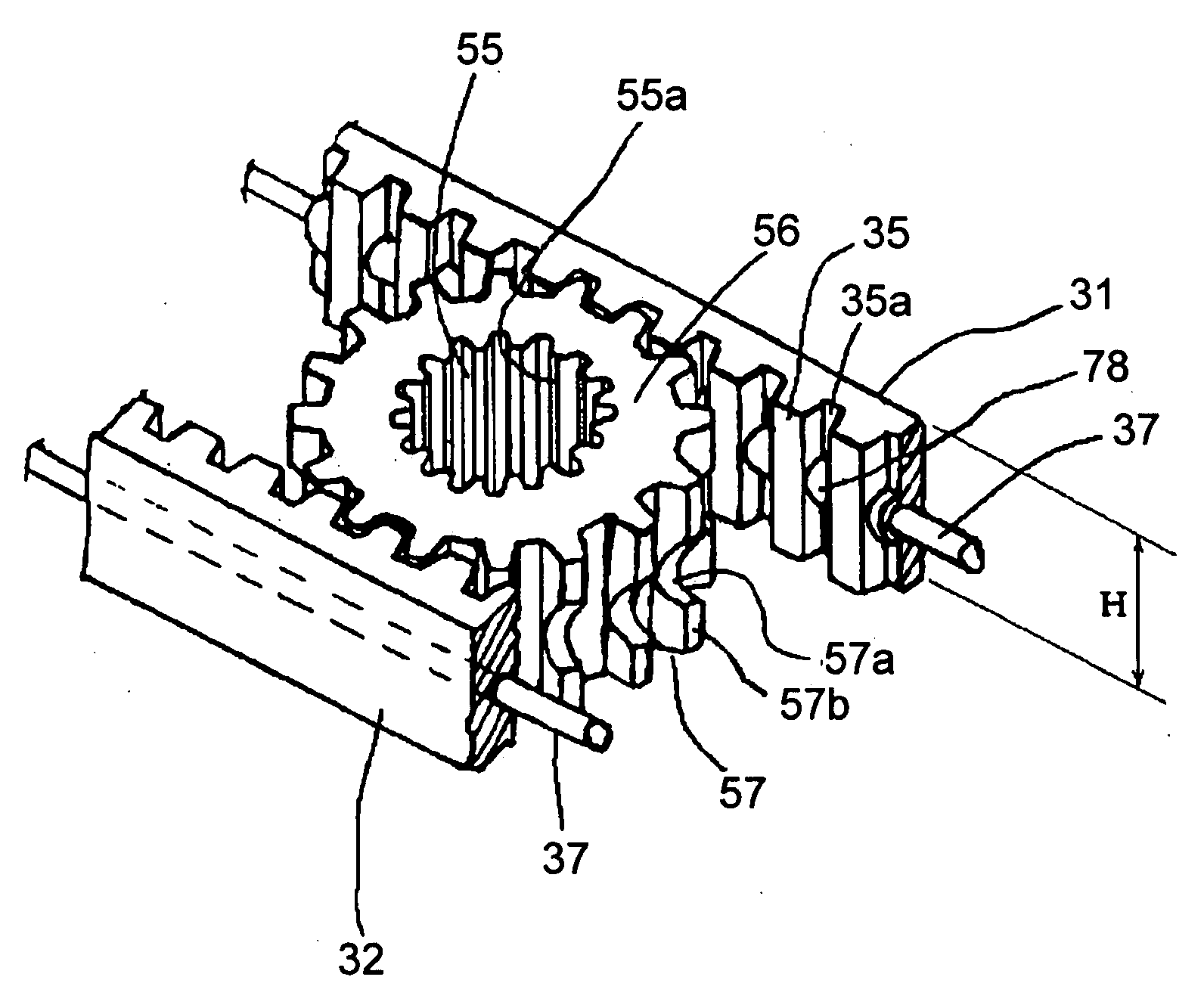
[0039]In the second embodiment, a guiding member 127 for guiding the rack belt 31 is made of a pipe including a hollow portion having a circular cross section. The rack belt 131 slides with contacting with an inner peripheral surface of the hollow portion of the guiding member 127 at three portions, each upper and lower surface of the rock teeth 135 and a contacting protruding portion 131a formed at a back surface of the rock teeth 135. A core wire 137 is embedded at a central portion of the rack belt 131. Specifically, the core wire 137 is embedded at the rack belt 131 at a position being identical with a center of the internal diameter of the guiding member 127. In the second embodiment, because of the existence of the contacting protruding portion 131a, stiffness in a vertical direction can be enhanced relative to the rack belt in the first embodiment. Further, when the guiding ...


PUM


Abstract

A sunroof apparatus for use in an automotive vehicle having a roof with an opening portion includes a movable panel, a supporting mechanism supporting the movable panel, an actuating device generating an actuating force for actuating the movable panel, a transmitting mechanism transmitting the actuating force, the transmitting mechanism having a rack belt made of resin and engaging with an actuating gear of the actuating device and a guiding member guiding the rack belt so as to be slidable, wherein the rack belt includes a plurality of longitudinally disposed and alternately spaced rack teeth and grooves, each of the grooves being provided with a protruding portion bridging two adjacent rack teeth at a mid portion of each groove, and a core wire embedded within the protruding portion of the rack belt so as to extend in a longitudinal direction of the rack belt.

Description

CROSS REFERENCE TO RELATED APPLICATIONS[0001]This application is based on and claims priority under 35 U.S.C. § 119 to Japanese Patent Application 2006-029837, filed on Feb. 7, 2006, the entire content of which is incorporated herein by reference.FIELD OF THE INVENTION[0002]The present invention relates to a sunroof apparatus. Specifically, the present invention relates to a configuration of a rack belt serving as means for transmitting an actuating force.BACKGROUND[0003]A known sunroof apparatus, which actuates a movable panel so that an opening portion provided at a roof of a vehicle is opened / closed, includes an actuating device and a transmitting mechanism for transmitting an actuating force generated by the actuating device to a supporting mechanism of the movable panel.[0004]More specifically, a sunroof apparatus disclosed in JP2001-130261A includes a geared cable used as the transmitting mechanism. The geared cable includes a cable portion and a gear portion, both of which ar...

Claims


Application Information

Patent Timeline
IPC IPC(8): B60J7/057
CPCB60J7/0573
Inventor MORI, KEIJINAGASHIMA, YOUJI
Owner AISIN SEIKI KK
Why Eureka
Try Eureka