DPLL circuit having holdover function

a holdover function and dpll technology, applied in the direction of generator stabilization, pulse automatic control, electrical equipment, etc., can solve the problems of temperature compensation operation limited, dds control value (tw) cannot be corrected, phase error signal cannot be generated, etc., to achieve the effect of suppressing frequency variation

Inactive Publication Date: 2007-08-09
FUJITSU LTD
View PDF5 Cites 16 Cited by
  • Summary
  • Abstract
  • Description
  • Claims
  • Application Information

AI Technical Summary

Benefits of technology

[0027] According to the present invention, the DPLL circuit calculates a correction value that offsets a frequency temperature change of a temperature obtained from a temperature sensor such as a thermistor, based on a tempe

Problems solved by technology

Therefore, when a trouble occurs in the reference clock, a phase error signal cannot be generated, and the DDS control value (TW) cannot be corrected.
However, t

Method used


Image

  • DPLL circuit having holdover function
  • DPLL circuit having holdover function
  • DPLL circuit having holdover function

Examples


first embodiment

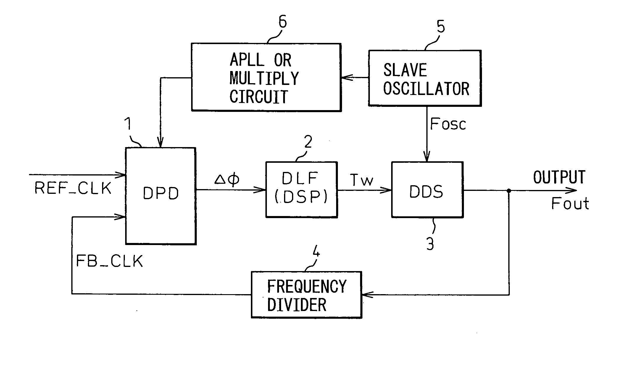
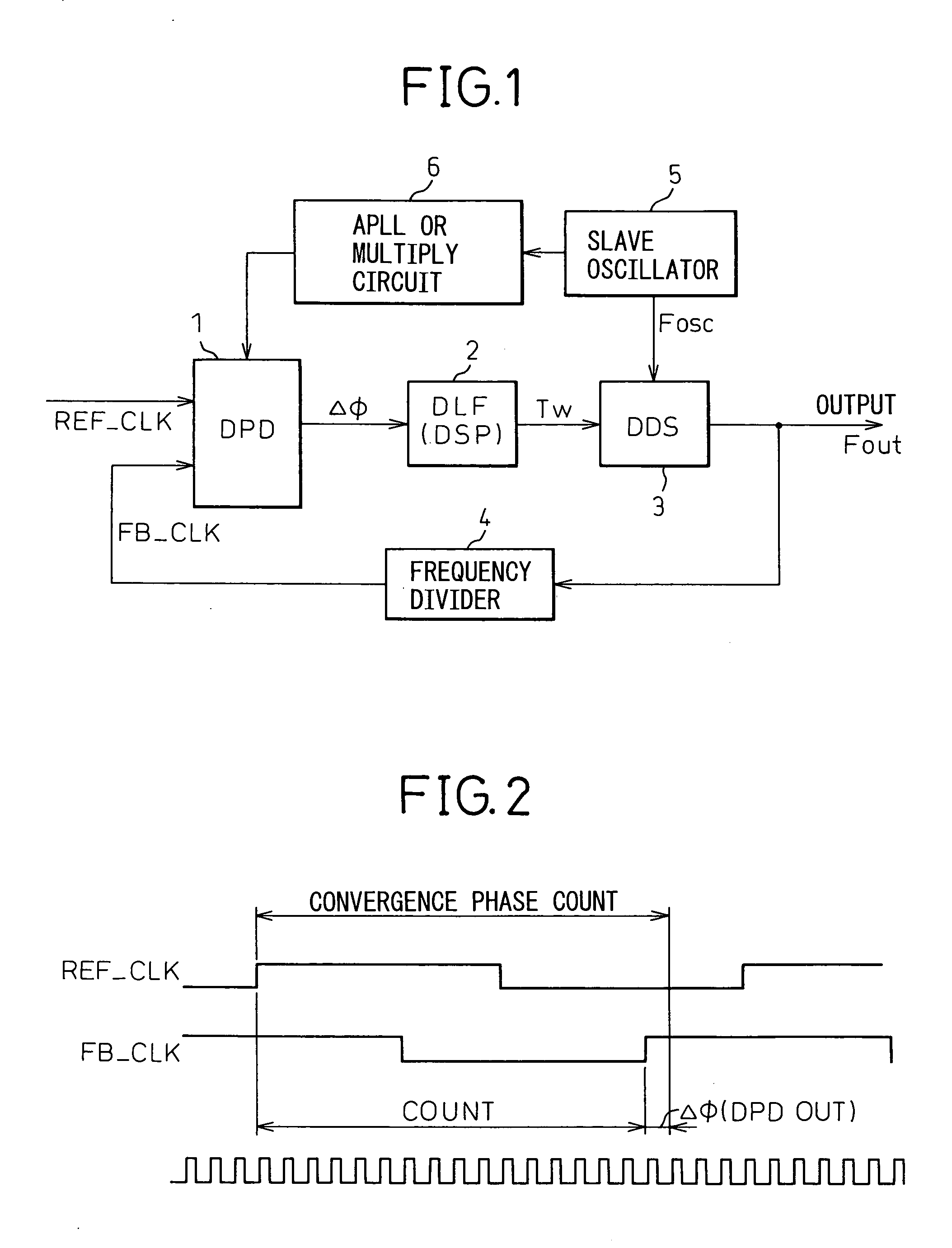
[0041]FIG. 5 is a block diagram of a DPLL circuit according to the present invention.

[0042] In FIG. 5, a temperature sensor 22, such as a thermistor, monitors the ambient temperature, and an A / D converter 23 converts this information into digital data. A correction value converter 24 calculates a temperature correction value, based on the digital data and a temperature characteristic 21 of the slave oscillator 5 determined in advance, and adds the calculated temperature correction value to the control value (i.e., a fixed value) during the holdover time as indicated by a reference numeral 14. The DPL circuit controls the DDS 3, using the correction value after the temperature correction.

second embodiment

[0043]FIG. 6 is a block diagram of a DPLL circuit according to the present invention.

[0044] A configuration of the DPLL is similar to that shown in FIG. 5, except that the DPLL converts a correction value based on a lookup table 31 stored in a memory. Using the lookup table is effective to simplify the calculation when the temperature characteristic of the oscillator is expressed in a two-dimensional curve or a three-dimensional curve.

[0045]FIG. 7 is a graph showing one example of a temperature characteristic of the slave oscillator 5.

[0046] As shown in FIG. 7, when the temperature characteristic can be approximated by a simple straight line or an exponential function as indicated by reference numeral 41, a configuration having no memory as shown in FIG. 5 is advantageous. On the other hand, when the temperature characteristic is expressed in a two-dimensional curve or a three-dimensional curve as indicated by a reference numeral 42, the configuration shown in FIG. 6 is advantageo...


PUM


Abstract

The invention relates to a digital synchronization network, and provides a DPLL circuit having a holdover function that generates a high-precision reference clock with a temperature correction to perform a free-running frequency control at a holdover time. In a holdover mode of the DPLL circuit using a DDS, the DPLL circuit having a holdover function adds a correction value calculated from a temperature characteristic of a slave oscillator to a fixed DDS control value during a detection of a holdover, thereby changing the DDS control value according to the temperature characteristic.

Description

TECHNICAL FIELD [0001] The present invention relates to a digital network synchronizer. Particularly, the invention relates to a digital phase-locked loop (DPLL) circuit having a holdover function that generates a high-precision reference clock, with temperature correction, to perform free-running frequency control during holdover time. BACKGROUND ART [0002] A general DPLL circuit will be briefly explained. FIG. 1 is a block diagram of a DPPL circuit. FIG. 2 is a graph showing an operation example of a digital phase detector (DPD) 1. FIG. 3 is an explanatory diagram of an operation example of a direct digital synthesizer (DDS) 3. [0003] In FIG. 1, a DPLL circuit includes the DPD 1, a digital loop filter (DLF) 2, a slave oscillator 5, an analog PLL or a multiply circuit 6 that generates a phase count clock, and a frequency divider 4 that converts an output frequency into an input frequency. As shown in FIG. 2, the DPD 1 counts the time between a rising edge of a reference clock (REF_...

Claims


Application Information

Patent Timeline
IPC IPC(8): H03L7/06
CPCH03L1/022H03L7/0994H03L1/025
Inventor NAKAMUTA, KOJI
Owner FUJITSU LTD
Why Eureka
Try Eureka