Tunable impedance surface and method for fabricating a tunable impedance surface

a technology of impedance surface and impedance surface, which is applied in the direction of antenna details, basic electric elements, antennas, etc., can solve the problem that the cost of such a phased array architecture may be dominated by the number of individual elements

Active Publication Date: 2007-08-09
RAYTHEON CO
View PDF10 Cites 71 Cited by
  • Summary
  • Abstract
  • Description
  • Claims
  • Application Information

AI Technical Summary

Problems solved by technology

The cost of such a phased array architecture may

Method used


Image

  • Tunable impedance surface and method for fabricating a tunable impedance surface
  • Tunable impedance surface and method for fabricating a tunable impedance surface
  • Tunable impedance surface and method for fabricating a tunable impedance surface

Examples


Embodiment Construction

[0017] In the following detailed description and in the several figures of the drawing, like elements are identified with like reference numerals.

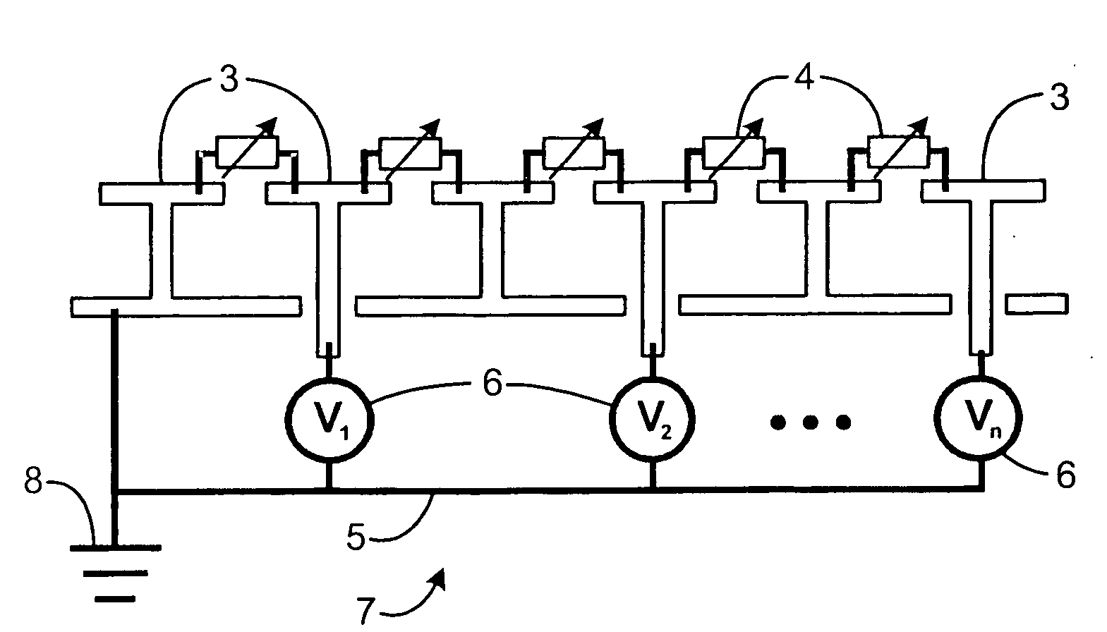
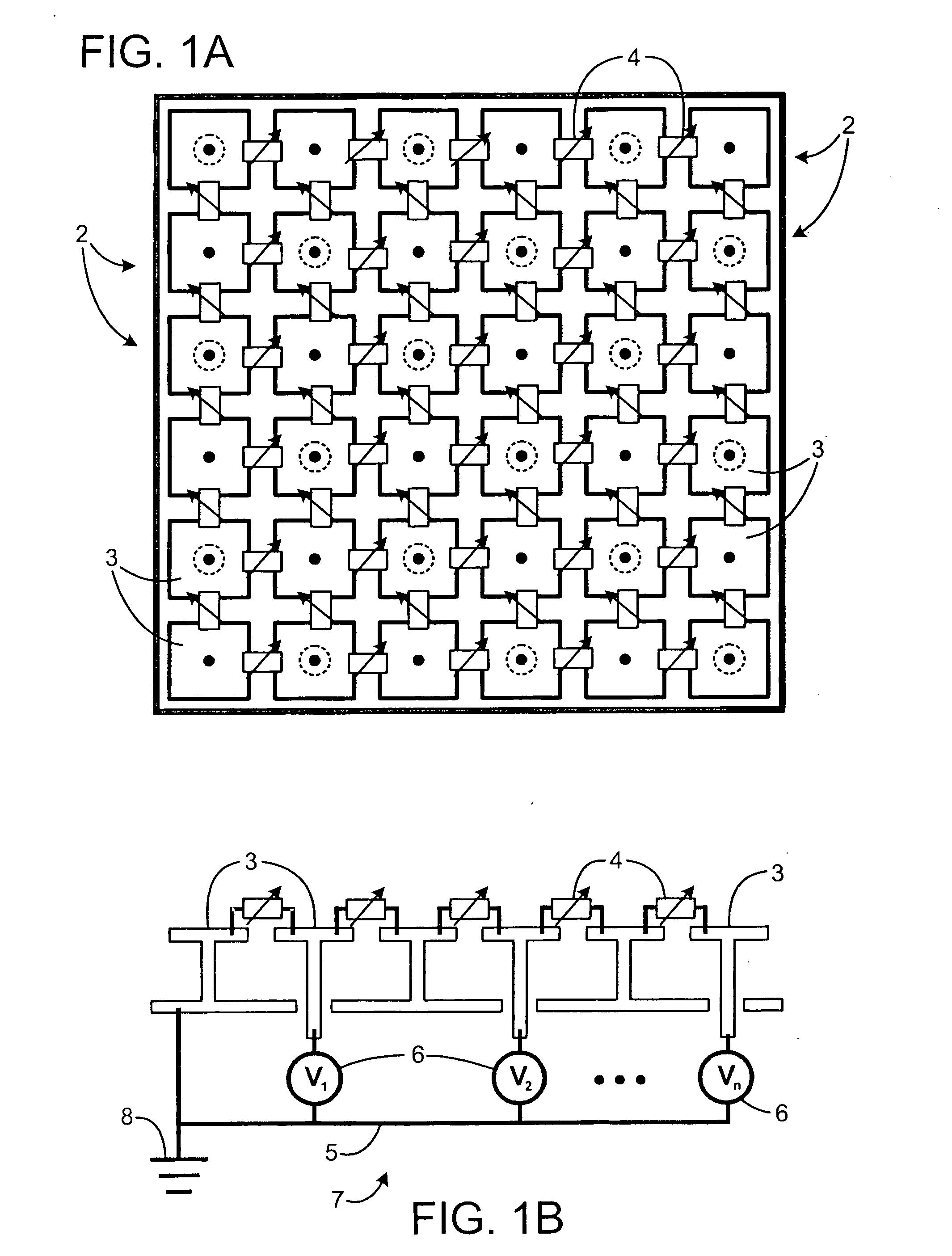
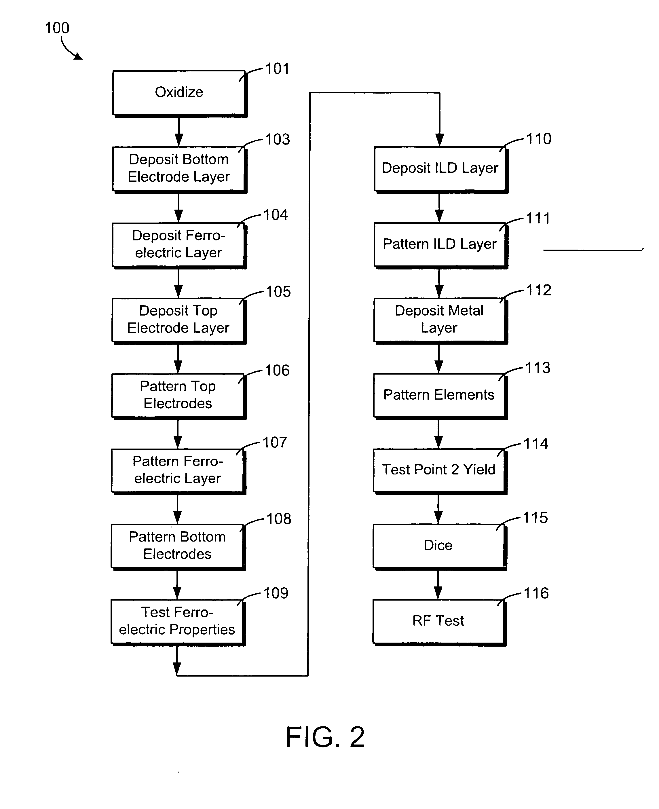
[0018]FIG. 1A illustrates a simplified circuit diagram of an exemplary embodiment of a tunable surface 1. In an exemplary embodiment, a tunable surface may be used in an electronically steerable antenna (ESA). The tunable surface 1 may be made using a monolithic fabrication process 100 (FIG. 2) as discussed below. The antenna may be capable of steering a beam of microwave or millimeter wave energy in one or two dimensions, using a set of electrical control signals. The antenna may include a substrate 202 (FIG. 3), a ground plane 308, 08 (FIGS. 4A, 4B, 5A and 5B) on the back of the substrate, a periodic metallic pattern 2 on the front of the substrate, metal elements or patches 3 within the metallic pattern 2 are separated by varactors 4, variable reactance devices, which comprise a ferroelectric material, e.g. barium strontium titanate (B...


PUM


Abstract

A tunable impedance surface includes a varactor. The varactor comprises a bottom electrode formed on a surface of a substrate. First and second ferroelectric elements are on top of the bottom electrode and electrically connected to one another through the bottom electrode. A first top electrode is on top of and electrically connected to the first ferroelectric element and a second top electrode is on top of and electrically connected to the second ferroelectric element.

Description

BACKGROUND OF THE DISCLOSURE [0001] Phased-array antenna architecture includes a number of individual, active antenna elements, associated control electronics, a beam forming network including phase shifters and power combiners, and a complex assembly. The cost of such a phased array architecture may be dominated by the number of individual elements. [0002] A tunable impedance surface for steering and / or focusing a radio frequency beam is described in commonly-assigned U.S. Pat. Nos. 6,483,480, 6,552,696 and 6,538,621 to Sievenpiper et al. SUMMARY [0003] A tunable impedance surface includes a varactor. The varactor comprises a bottom electrode formed on a surface of a substrate. First and second ferroelectric elements are on top of the bottom electrode and electrically connected to one another through the bottom electrode. A first top electrode is on top of and electrically connected to the first ferroelectric element and a second top electrode on top of and electrically connected t...

Claims


Application Information

Patent Timeline
IPC IPC(8): H01Q1/38H01Q15/02
CPCH01Q15/008
Inventor SIEVENPIPER, DANIEL F.DOUGHERTY, THOMAS K.DRAB, JOHN J.ROBINSON, SOLOMON O.
Owner RAYTHEON CO
Why Eureka
Try Eureka