Variable Matching Circuit

a matching circuit and circuit technology, applied in the field of matching circuits, can solve the problems of difficult radio device to adapt to a wide range of frequency bandwidths, inability to fully exert the performance of the radio device, and high cos

Inactive Publication Date: 2008-10-02
PANASONIC CORP
View PDF0 Cites 50 Cited by
  • Summary
  • Abstract
  • Description
  • Claims
  • Application Information

AI Technical Summary

Benefits of technology

[0010]a second capacitance circuit of which element value is variable.The matching circuit has a first terminal and a second terminal, either one of which terminals work as an input or an output, and the second capacitance circuit is coupled between the first terminal and the second terminal. The resonator-type circuit is coupled between the first terminal and the grounding. An inductance value of the inductance circuit can be switched with a combination of plural inductors and a switch into a plural values, thereby controlling the matching circuit.
[0012]The foregoing structure allows an L-shaped or π-shaped matching circuit to vary a capacitance value in the reactance circuit coupled in series as well as an inductance value in the reactance circuit coupled in shunt, so that a variable matching circuit highly adjustable in a wide range of frequency bandwidths is obtainable.

Problems solved by technology

However, an appropriate signal process, such as amplification, selection, and frequency conversion of a high frequency signal of radio frequency, needs a well matching between the elements of a circuit, otherwise the radio device cannot fully exert its performance.
The radio section thus requires a wider space for mounting in the radio device, and a chip area for integrating the functions into a semiconductor increases, which results in an expensive cost.
It is thus difficult for the radio device to adapt itself to a wide range of frequency bandwidths.

Method used


Image

  • Variable Matching Circuit
  • Variable Matching Circuit
  • Variable Matching Circuit

Examples


embodiment 1

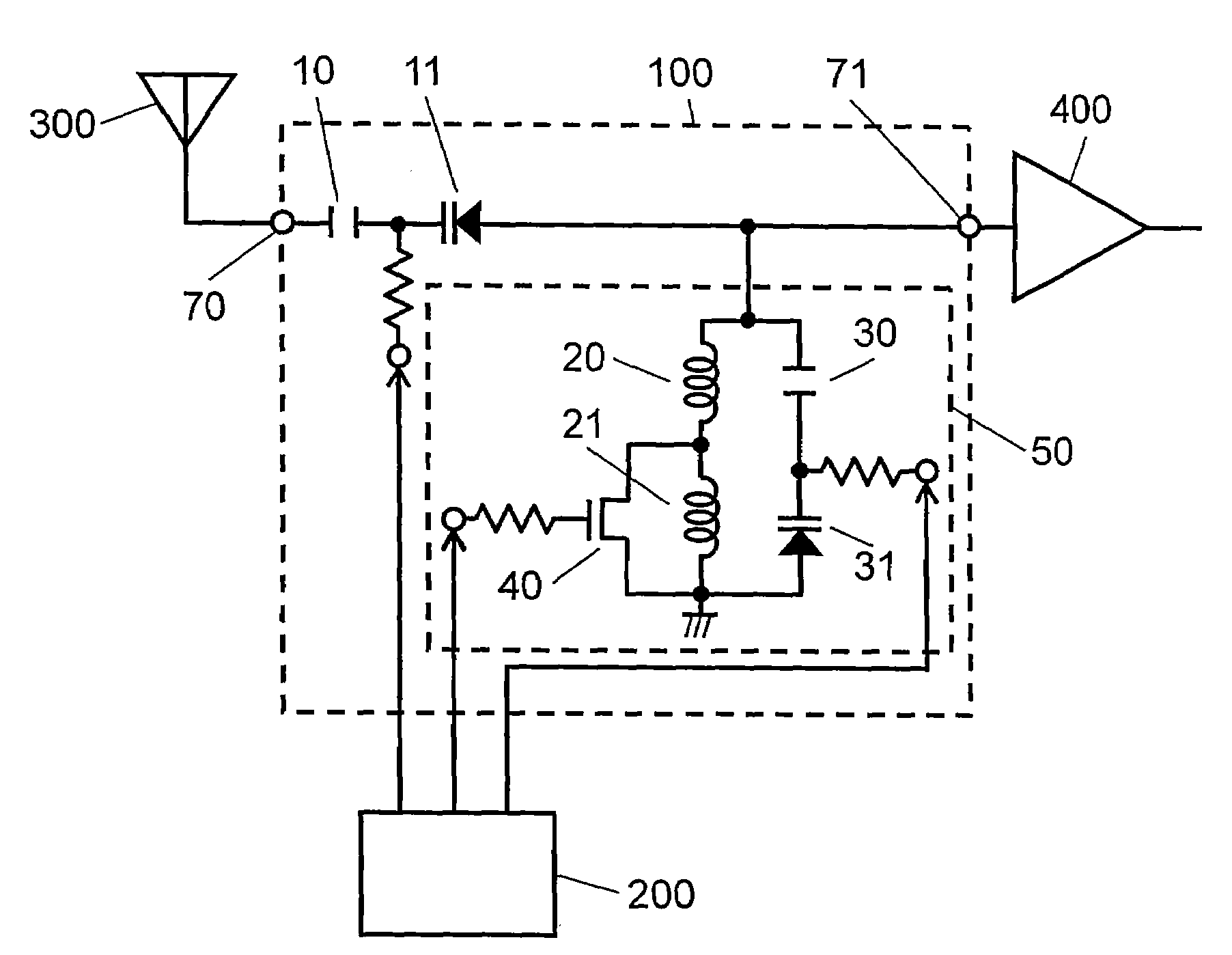
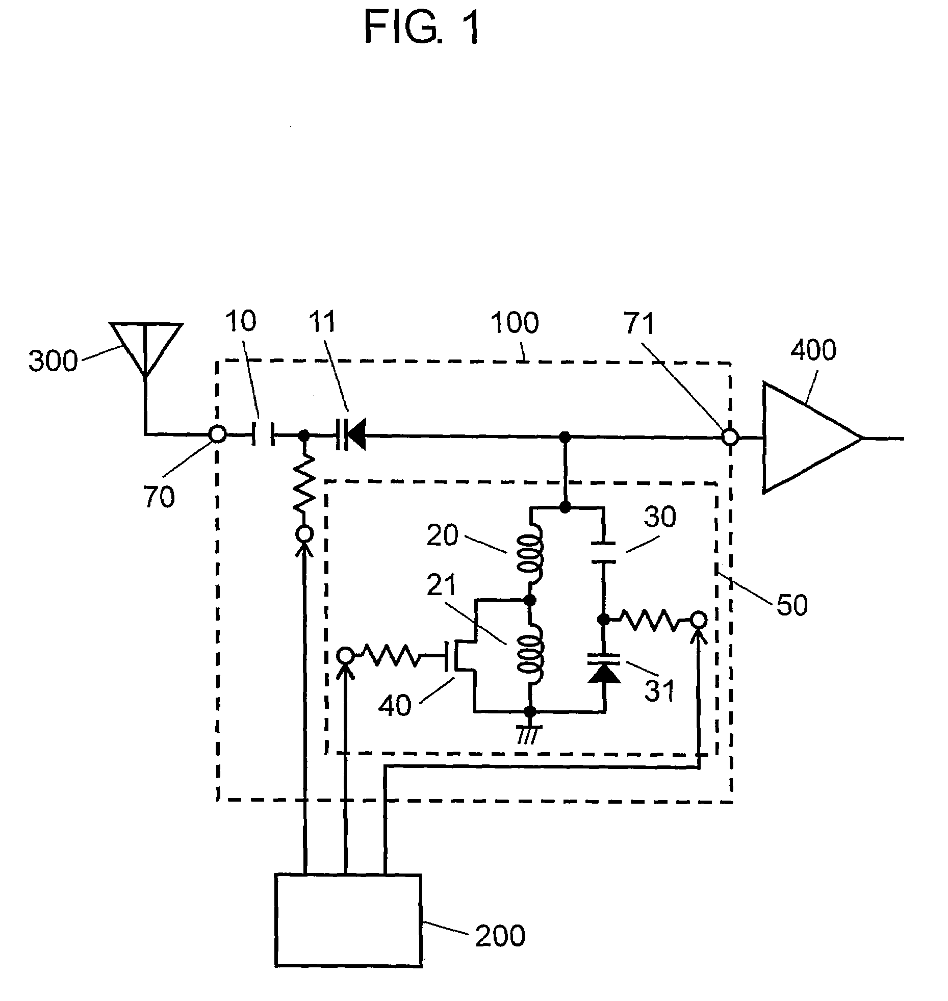
[0050]FIG. 1 shows a structure of a variable matching circuit in accordance with the first embodiment. In FIG. 1, terminals 70 and 71 work as input / output terminals of variable matching circuit 100. Capacitor 10 and varactor diode 11 form a capacitance circuit having a variable capacitance coupled between the foregoing two terminals, and this capacitance circuit forms a second capacitance circuit of the present invention. Resonator-type circuit 50 is grounded via terminal 71, and includes a capacitance circuit formed of capacitor 30 and varactor diode 31, which capacitance circuit corresponds to a first capacitance circuit of the present invention, and an inductance circuit formed of two inductors 20, 21 coupled in series. The capacitance circuit is coupled in parallel to the inductance circuit. Inductors 20, 21 are grounded via FET (field effect transistor) 40. External elements are coupled to variable matching circuit 100 such as varactor diodes 11, 31 and impedance controller 200...

embodiment 2

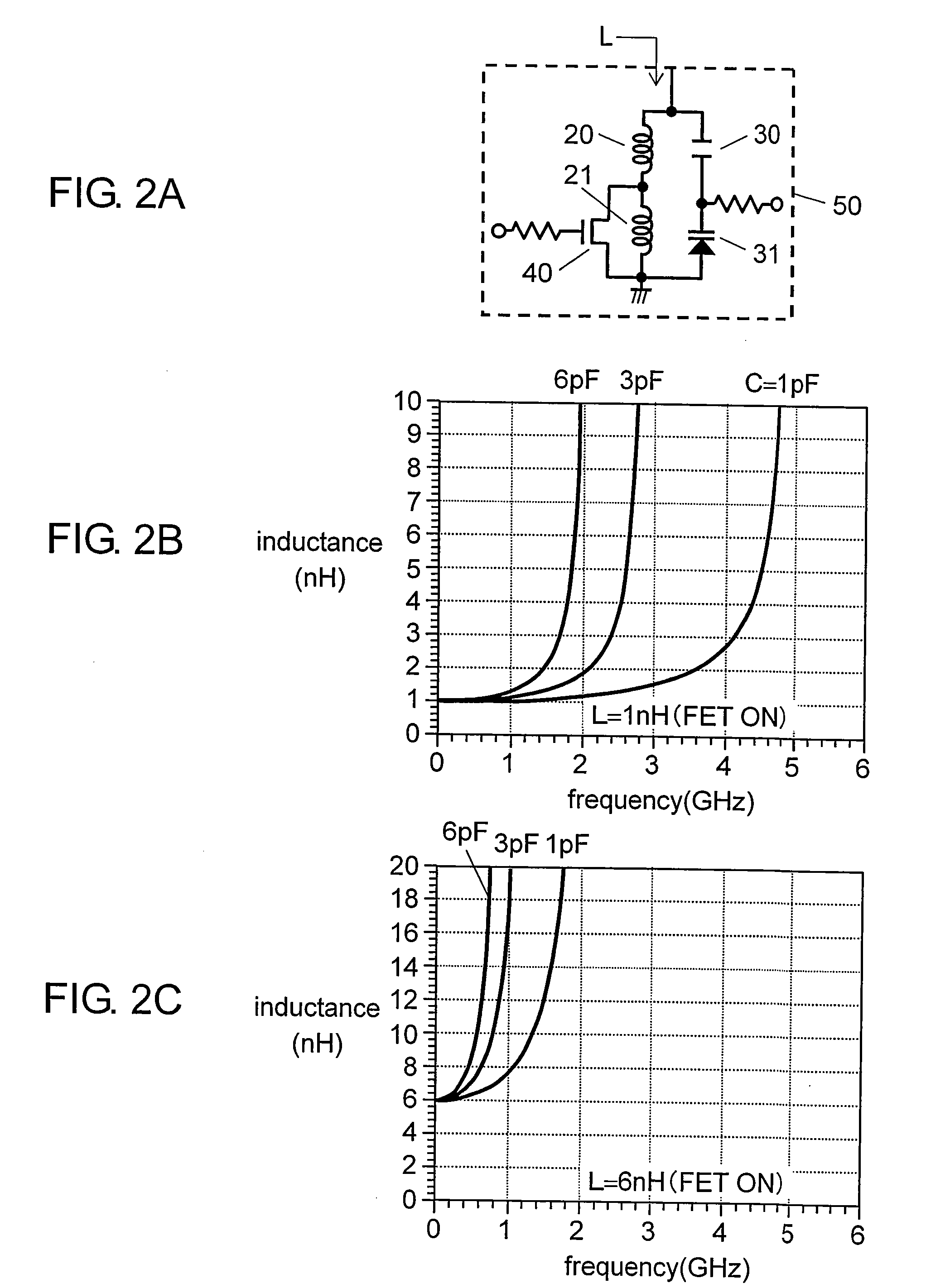
[0078]FIG. 6 shows a structure of a variable matching circuit in accordance with the second embodiment of the present invention. This structure differs from that shown in FIG. 1 in providing terminals 70 and 71 with first resonator-type circuit 53 and second resonator-type circuit 54 of the present invention respectively. Resonator-type circuits 53 and 54 are schematically shown in FIG. 6 for simple description; however, the actual circuits are similar to resonator-type circuit 50 shown in FIG. 2A and resonator-type circuit 51 or 52 shown in FIG. 4A or FIG. 4B. An operation of circuits 53 and 54 is demonstrated hereinafter, although their basic operation is similar to that described in the first embodiment.

[0079]In FIG. 6, an L-type matching circuit, formed of a seriesly coupled capacitor and a shunt inductor, converts an impedance within a limited range. In this second embodiment, the resonator-type circuits of the present invention are thus provided to both of the input and output...

embodiment 3

[0093]FIG. 8A shows a structure of a variable matching circuit in accordance with the third embodiment. This structure differs from the one shown in FIG. 1 in providing distributed constant line 60 between terminal 71 and resonator-type circuit 55 as well as distributed constant line 61 between terminal 71 and varactor diode 11. Resonator-type circuit 55 shown in FIG. 8A is schematically illustrated for a simple description, but its actual structure is similar to resonator-type circuit 50 shown in FIG. 2A, resonator-type circuit 51 shown in FIG. 4A, or resonator-type circuit 52 shown in FIG. 4B. Resonator-type circuit 55 basically works similarly to the variable matching circuit demonstrated in the first embodiment.

[0094]The variable matching circuit includes the capacitance circuit employing varactor diode 11 and corresponding to the second capacitance circuit of the present invention, so that the capacitance can be varied sequentially. The components to be actually used such as a ...


PUM


Abstract

A variable matching circuit includes a variable capacitance circuit formed of a capacitor coupled to varactor diode and provided between terminals, and a resonator-type circuit includes a plurality of inductors and a variable capacitance circuit formed of a capacitor and a varactor diode. The inductors and the variable capacitance circuit are coupled in parallel together. The resonator-type circuit is connected in shunt with the terminal. The foregoing structure forms an L-type matching circuit. The bias of the varactor diodes can be thus varied, and plural values of the inductance of the resonator-type circuit can be switched over with a FET. The variable matching circuit can electrically control an impedance conversion available for wider ranges of frequency bandwidths.

Description

TECHNICAL FIELD[0001]The present invention relates to matching circuits electrically controllable over an impedance conversion, which matching circuits are employed in radio devices using a plurality of radio frequency bands higher than or equal to UHF band.BACKGROUND ART[0002]Recently, personal wireless systems such as a data communication system, used by a portable telephone called a cellular phone, and a wireless LAN built by a personal computer, have been widely used. Reception of digital television broadcasting on the ground wave with a portable personal wireless terminal has been studied in progress. Infrastructure of various wireless systems has been built as discussed above. Amid the foregoing circumstances, personal information terminals including typically a cellular phone are required to make plural and yet different wireless systems available within one information terminal for users' convenience. On the other hand, a cellular system provides a service employing a wider ...

Claims


Application Information

Patent Timeline
Patent Type & Authority Applications(United States)
IPC IPC(8): H03H7/38H03H7/40H04B1/18
CPCH03H7/40H04B1/18
Inventor MATSUO, MICHIAKI
Owner PANASONIC CORP
Why Eureka
Try Eureka