Display device and driving method thereof

a technology of a display device and a driving method, which is applied in the direction of static indicating devices, instruments, etc., can solve the problems of inability to accurately correct changes in luminance, increase in size, and inability to maintain constant luminance of a display light emitting element, so as to achieve the effect of ensuring constant luminance, easy configuration and accurate correction of changes in luminan

Inactive Publication Date: 2007-08-09
SEMICON ENERGY LAB CO LTD
View PDF48 Cites 17 Cited by
  • Summary
  • Abstract
  • Description
  • Claims
  • Application Information

AI Technical Summary

Benefits of technology

[0032] According to the invention, a circuit for compensating changes in temperature and changes with time is provided in a display device; thereby the luminance of a displaying light emitting element can be kept constant. This compensation circuit can be easily configured by a current source, a monitoring light emitting element and a voltage generating circuit. Further, changes in luminance can be corrected while driving the displaying light emitting element without previously obtaining degradation characteristics of the light emitting element.
[0033] According to the invention, the amount of charge flowing through the displaying light emitting element is compared to that flowing through the monitoring light emitting element by taking luminance degradation into consideration based on the amount of charge flowing through the light emitting element; thereby the CL drive can be performed where the luminance of the displaying light emitting element can be corrected to be constant. Since the invention uses a constant voltage drive, the light emitting element can be driven at a lower voltage as compared to the case of using a constant current drive, leading to reduced power consumption.

Problems solved by technology

In conventional technologies, however, a corrected current value is determined by an external device such as a computer in order to keep the luminance of a light emitting element constant, in which case a display device is inevitably complicated and increased in size.
Further, even when degradation characteristics of a light emitting element are previously stored in a computer, there are variations in characteristics of the light emitting element and the degradation characteristics vary at random depending on hysteresis of the light emitting element such as driving conditions.
Accordingly, it is not possible to correct changes in luminance accurately.

Method used


Image

  • Display device and driving method thereof
  • Display device and driving method thereof
  • Display device and driving method thereof

Examples


embodiment 1

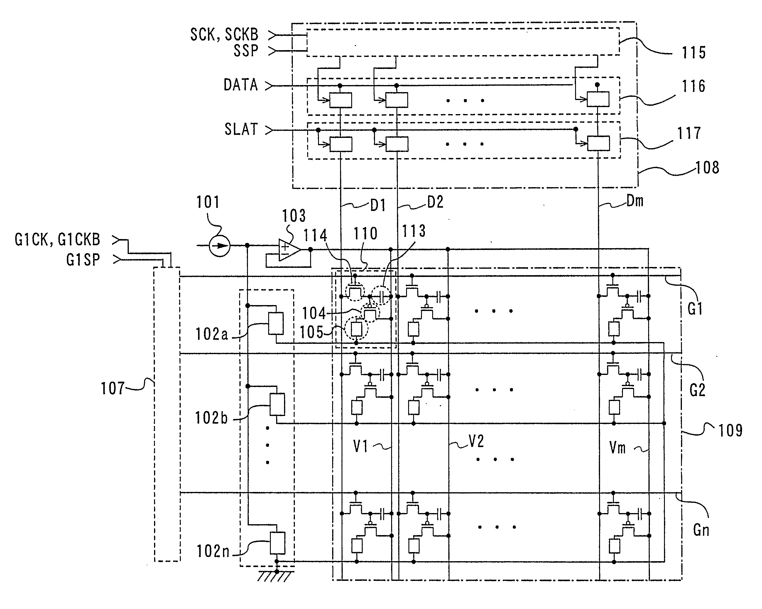
[0119] An example of a display device provided with a monitoring light emitting element and performing the CL drive is described with reference to FIG. 7.

[0120] A display device shown in FIG. 7 includes the scan line driver circuit 107, the data line driver circuit 108 and the display portion 109. The display portion 109 includes the pixel 110 where a switching transistor 114, the driving transistor 104, a capacitor 113, and the displaying light emitting element 105 are provided.

[0121] The data line driver circuit 108 includes a pulse output circuit 115, a first latch circuit 116 and a second latch circuit 117. In this data line driver circuit 108, data can be outputted from the second latch circuit 117 at the same time as data is inputted to the first latch circuit 116.

[0122] The display portion 109 includes scan lines G1 to Gn connected to the scan line driver circuit 107 and data signal lines D1 to Dm connected to the data line driver circuit 108. The scan line G1 to which a s...

embodiment 2

[0133] This embodiment shows another configuration example of a display device performing the CL drive by combining a monitoring light emitting element and a displaying light emitting element.

[0134] In this embodiment, the amount of current, namely the amount of charge of a monitoring light emitting element is determined taking into consideration the average lighting period of a displaying light emitting element in a pixel. It is experimentally known that the average ratio of a lighting period to a non-lighting period of a displaying light emitting element in each pixel is 3:7. By adjusting a lighting period of the monitoring light emitting element, the amount of charge Qm of the monitoring light emitting element and the amount of charge Qp of the displaying light emitting element can be controlled so that g(Qp) / g(Qm) is close to exp{(k·t)η} as represented by the formula (12). The duty ratio of the monitoring light emitting element may be set to 50 to 100%.

[0135]FIG. 10 shows an e...

embodiment 3

[0142] This embodiment shows a configuration example of a display device performing the CL drive by combining a monitoring light emitting element and a displaying light emitting element, where a correction function of the monitoring light emitting element can be maintained for a long time.

[0143]FIG. 11 shows an example of a compensation circuit for correcting degradation with time of a monitoring light emitting element. This compensation circuit includes the current source 101, the monitoring light emitting element 102a, the monitoring light emitting element 102b, the voltage generating circuit 103, and a switch circuit 126 having a switch 126a and a switch 126b. The output of the voltage generating circuit 103 is inputted to the displaying light emitting element 105 through the driving transistor 104.

[0144] The switch 126a and the switch 126b switch a connection with the current source 101 between the monitoring light emitting element 102a and the monitoring light emitting elemen...


PUM


Abstract

In order to keep the luminance of a light emitting element constant, the correction is performed by an external device such as a computer, in which case a display device is inevitably complicated and increased in size. Even when degradation characteristics of the light emitting element are previously stored in a computer, the degradation characteristics vary at random depending on hysteresis of the light emitting element; therefore, changes in luminance cannot be corrected. According to the invention, a display device includes a displaying light emitting element provided in a display portion and a plurality of monitoring light emitting elements having the similar characteristics as the displaying light emitting element. At least one of the monitoring light emitting elements is operated under a condition different from the displaying light emitting element, and the ratio of the total amount of charge flowing through the displaying light emitting element to that flowing through the monitoring light emitting element is controlled to satisfy a certain relation in view of luminance degradation. When the one monitoring light emitting element reaches a predetermined voltage or time, the connection is switched from the one monitoring light emitting element to another monitoring light emitting element that has been operated under the same condition as the displaying light emitting element.

Description

TECHNICAL FIELD [0001] The present invention relates to a display device and a driving method thereof, and more particularly relates to a display device using a light emitting element. BACKGROUND ART [0002] A display device including a display screen formed by a light emitting element using an electro luminescence (hereinafter also referred to as EL) material has been developed. There are known a plurality of driving methods and panel configurations for such a display device. For example, known is a technology where a light emitting element for monitoring temperature is provided in a panel so that a constant current is supplied to a light emitting element of a pixel even when the ambient temperature varies (see Patent Document 1, for example). [0003] Another display device is also disclosed, which includes a display panel formed by a plurality of light emitting portions, a driving means for supplying a constant current driving signal in accordance with an inputted signal, a detectin...

Claims


Application Information

Patent Timeline
Patent Type & Authority Applications(United States)
IPC IPC(8): G09G3/30
CPCG09G3/3258G09G2320/029G09G2320/048G09G2320/041G09G2320/045G09G2320/0295
Inventor YAMAZAKI, SHUNPEIKOYAMA, JUNSEO, SATOSHIABE, HIROKOOSAME, MITSUAKI
Owner SEMICON ENERGY LAB CO LTD
Why Eureka
Try Eureka