
Apparatus to fabricate color filter and method thereof

a technology of color filter and apparatus, applied in the direction of instruments, coatings, pretreated surfaces, etc., can solve the problems of affecting the quality of the panel, increasing the fabrication cost, and reducing the efficiency of the process

Inactive Publication Date: 2007-08-09
SAMSUNG ELECTRONICS CO LTD
View PDF13 Cites 4 Cited by
  • Summary
  • Abstract
  • Description
  • Claims
  • Application Information

AI Technical Summary

Benefits of technology

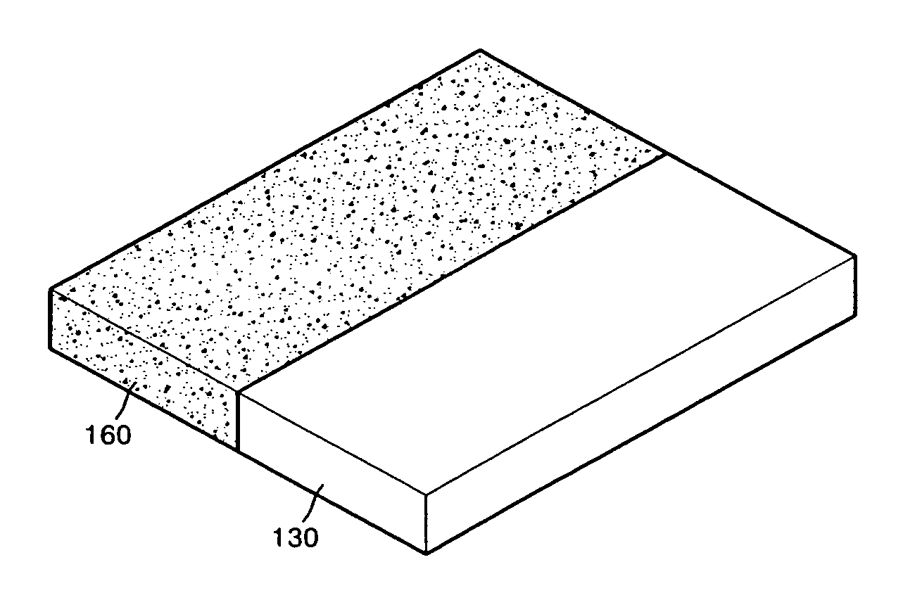
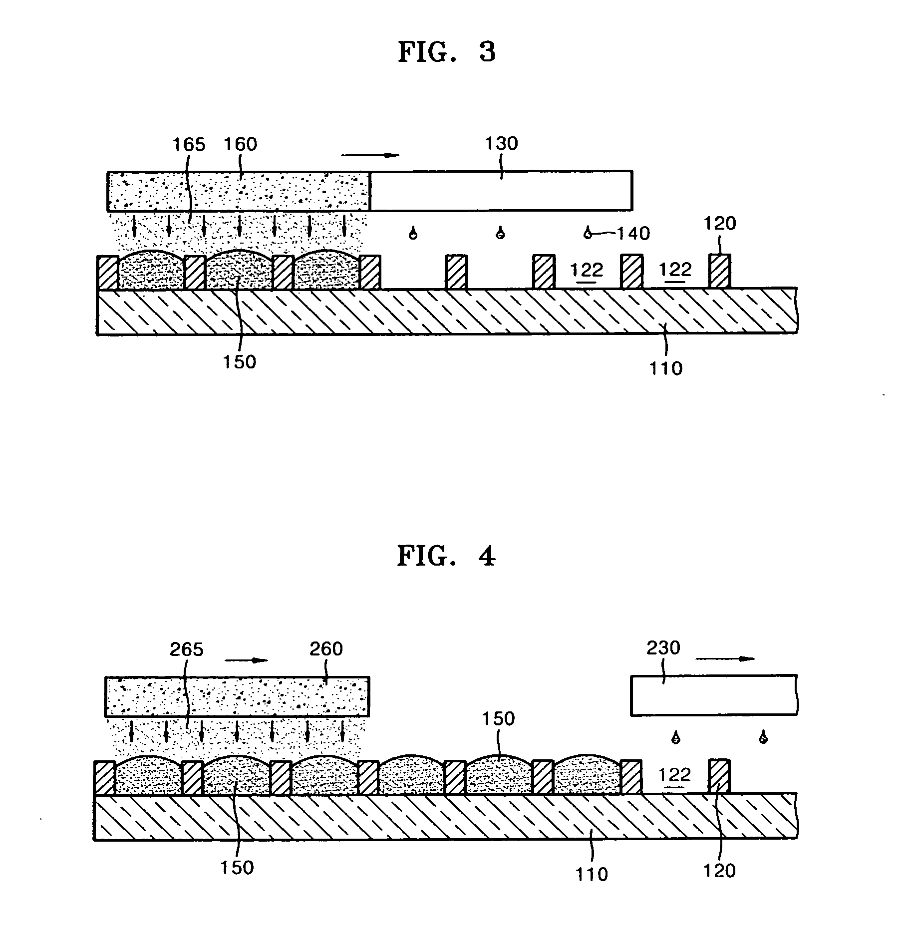
[0011]The foregoing and / or other aspects and utilities of the present general inventive concept may be achieved by providing an apparatus to fabricate a color filter, the apparatus including an inkjet head movably installed over a substrate to discharge ink of predetermined colors into pixels formed on the substrate, and a porous member movably installed over the pixels to form a solvent ambient around the ink discharged into the pixels due to an evaporation of a solvent in the porous member to reduce a drying speed of the ink discharged into the pixels.
[0020]The foregoing and / or other aspects and utilities of the present general inventive concept may also be achieved by providing a system to fabricate a color filter, including an inkjet printhead to discharge ink, and a porous member to supply a solvent toward the discharged ink. The system may further include a substrate having a plurality of pixels, the ink may be filled in the plurality of pixels, and the solvent may be supplied over the ink filled in the plurality of pixels. The plurality of pixels may include a plurality of first sub-pixels and a plurality of second sub-pixels, and the porous member may supply a first amount of the solvent to the first sub-pixels and a second amount of the solvent to the second sub-pixels. The porous member may maintain a uniform solvent ambient around the pixels to control a drying speed of the ink in the pixels.

Problems solved by technology

However, these conventional methods include a repetition of predetermined processes for pixels of each color, thus degrading process efficiency and increasing fabrication costs.
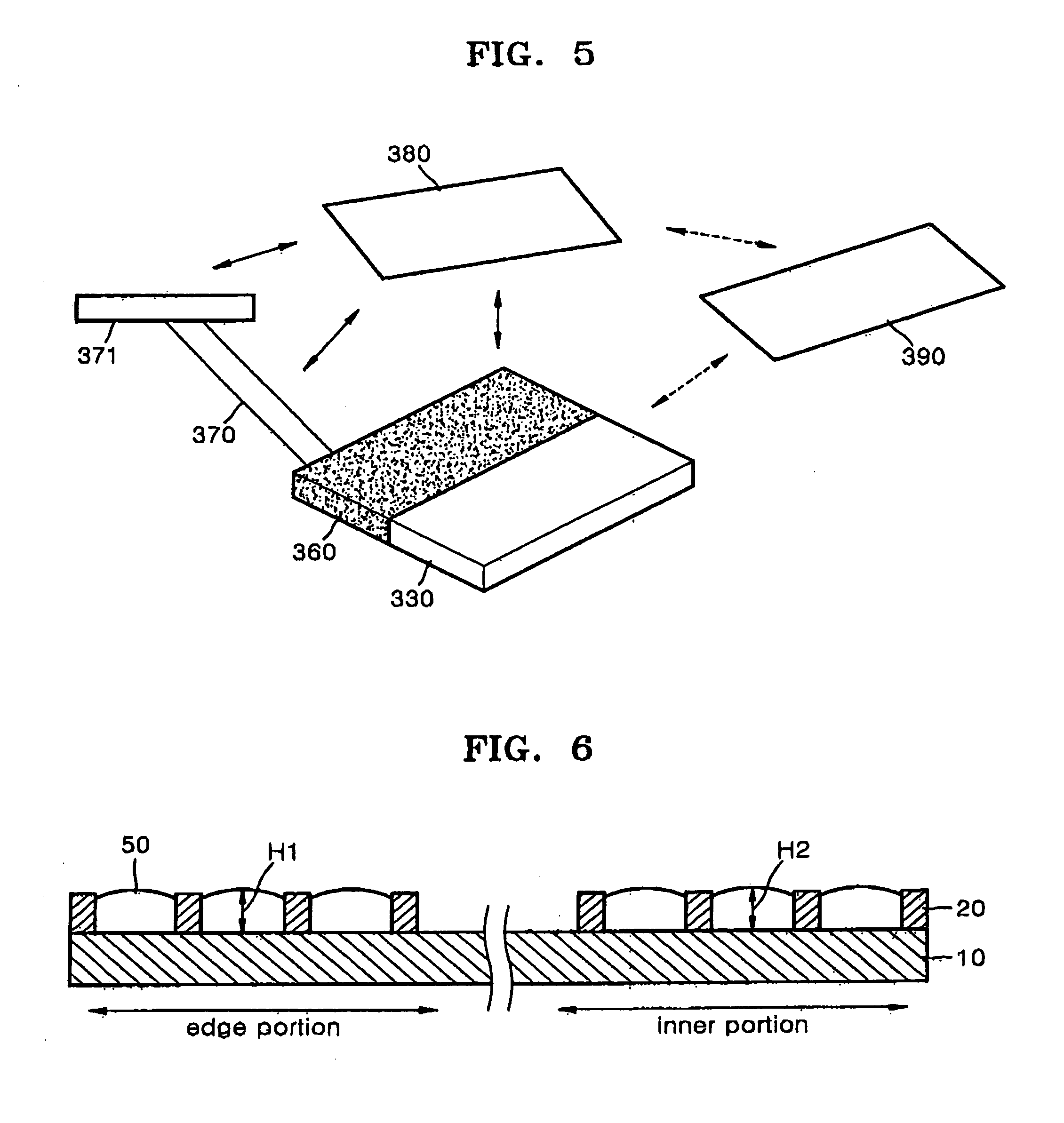
Furthermore, since the pixels 22 having ink layers with a large thickness variation are concentrated on a specific location of the color filter, that is, on the edge portions of the color filter, a quality of a panel is negatively affected, such as by a generation of a blurry image.

Method used


Image

  • Apparatus to fabricate color filter and method thereof
  • Apparatus to fabricate color filter and method thereof
  • Apparatus to fabricate color filter and method thereof

Examples


Embodiment Construction

[0031]Reference will now be made in detail to the embodiments of the present general inventive concept, examples of which are illustrated in the accompanying drawings, wherein like reference numerals refer to the like elements throughout. In the drawings, the thicknesses of elements are exaggerated for clarity. The embodiments are described below in order to explain the present general inventive concept by referring to the figures.

[0032]FIG. 2 is a perspective view illustrating an apparatus to fabricate a color filter according to an embodiment of the present general inventive concept. FIG. 3 illustrates a method of fabricating the color filter using the apparatus of FIG. 2. Referring to FIGS. 2 and 3, the apparatus to fabricate the color filter includes an inkjet head 130 and a porous member 160 attached to the inkjet head 130. The inkjet head 130 is movably placed over a substrate 110 a predetermined distance away from the substrate 110. The inkjet head 130 includes a plurality of...


PUM


Abstract

An apparatus to fabricate a color filter includes an inkjet head movably installed over a substrate on which a plurality of pixels are formed to discharge ink of predetermined colors into the pixels, and a porous member movably installed over the pixels filled with the ink discharged from the inkjet head to form a solvent ambient around the ink filled within the pixels due to evaporation of a solvent filled in the porous member to reduce a drying speed of the ink.

Description

CROSS-REFERENCE TO RELATED APPLICATIONS[0001]This application claims priority under 35 U.S.C. §119(a) from Korean Patent Application No. 10-2006-0012604, filed on Feb. 9, 2006, in the Korean Intellectual Property Office, the disclosure of which is incorporated herein in its entirety by reference.BACKGROUND OF THE INVENTION[0002]1. Field of the Invention[0003]The present general inventive concept relates to an apparatus to fabricate a color filter, and more particularly, an apparatus to fabricate a color filter in which ink layers having uniform thicknesses are formed within pixels of the color filter and a method thereof.[0004]2. Description of the Related Art[0005]Until recently, cathode ray tube (CRT) monitors have been usually used to display information from TVs and computers. However, flat panel displays, such as liquid crystal displays (LCDs), plasma display panels (PDPs), electro-luminescence (EL) displays, light emitting diodes (LEDs), and field emission displays (FEDs), are...

Claims


Application Information

Patent Timeline
IPC IPC(8): B05D5/00B05D3/10B41J2/01
CPCG02B5/201G02F1/133516G02B5/223G02F1/1335
Inventor BAEK, SEOG-SOONKIM, SEONG-JINSHIN, SEUNG-JOO
Owner SAMSUNG ELECTRONICS CO LTD
Learn More