Liquid ejector cleaning method and liquid ejector

US20070182779A1Inactive Publication Date: 2007-08-09SEIKO EPSON CORP

Image

  • Liquid ejector cleaning method and liquid ejector
  • Liquid ejector cleaning method and liquid ejector
  • Liquid ejector cleaning method and liquid ejector

Examples


Embodiment Construction

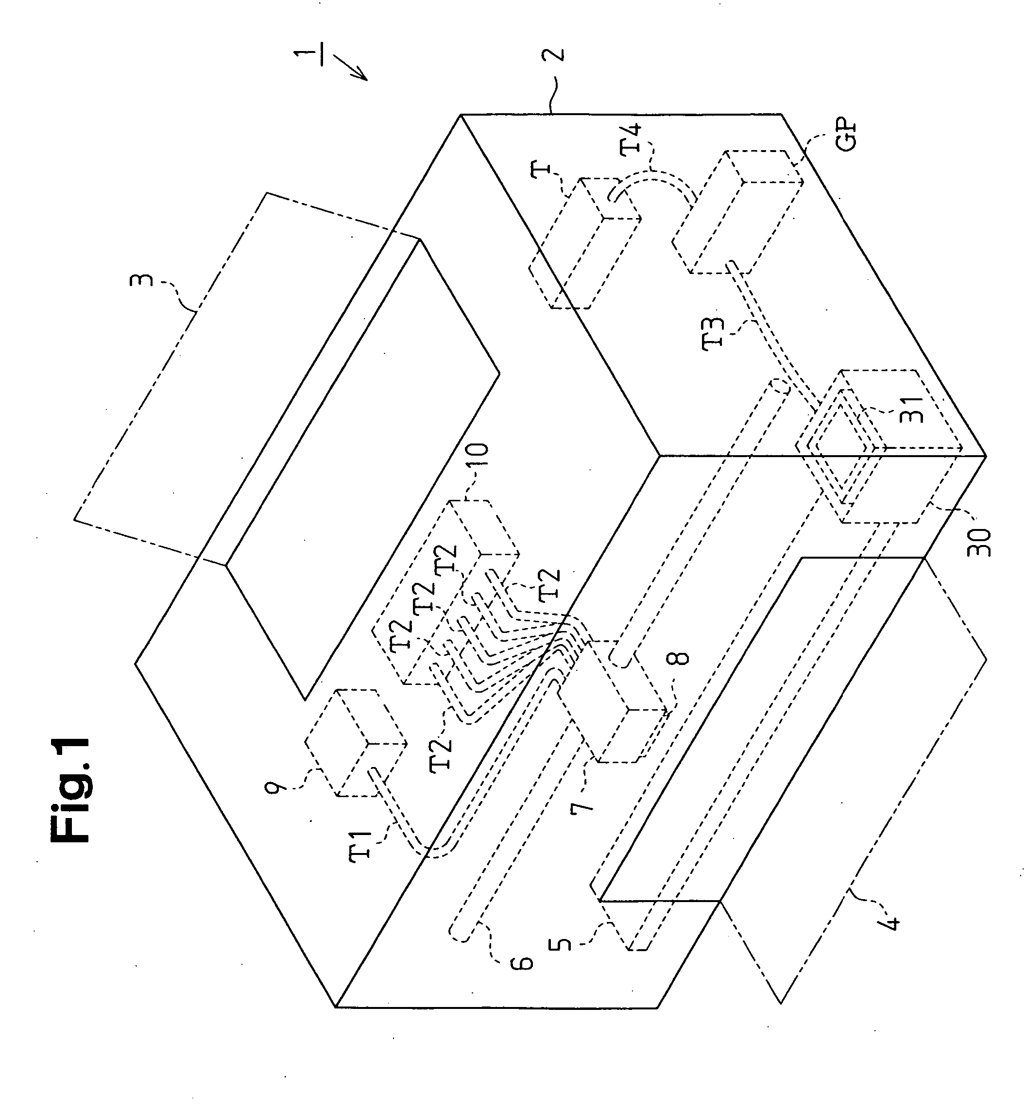
[0026] One embodiment of the present invention will be described hereinafter with reference to FIGS. 1 through 5. FIG. 1 is a schematic perspective view showing an inkjet recording device (hereinafter referred to simply as “printer”), which serves as a liquid ejector.

[0027] As shown in FIG. 1, a printer 1 includes an outer case 2 and a platen 5, which is arranged in the outer case 2. A recording sheet (not shown), which serves as a target, is fed from a paper tray 3 and inserted into the outer case 2 by a paper feeding mechanism (not shown) toward the platen 5. The fed recording sheet is discharged out of the outer case 2 from a discharge tray 4 by the paper feeding mechanism.

[0028] A guide member 6 is arranged in the outer case 2 parallel to the longitudinal direction of the platen 5. A carriage 7 is supported by the guide member 6 so as to be movable along the guide member 6. A carriage motor (not shown) is arranged in the outer case 2. The carriage motor drives the carriage 7 w...


PUM


Abstract

Recording head of a printer is sealed by a cap connected with a gear pump. Fluid is discharged from a nozzle through the cap by a negative pressure being generated by the gear pump. The gear pump is driven at a first rotational speed to suck the fluid in the cap and to discharge the fluid from the nozzle. Subsequently, the gear pump is driven at a second rotational speed lower than the first rotational speed and then it is stopped. This prevents backflow of the fluid to a liquid ejection head and breakage of a liquid meniscus in the nozzle of the liquid ejection head occurring when cleaning of the liquid ejection head is ended.

Description

FIELD OF THE INVENTION [0001] The present invention relates to a method for cleaning a liquid ejector and to a liquid ejector. BACKGROUND OF THE INVENTION [0002] Inkjet type recording devices (hereinafter referred to individually simply as a “printer”) are widely known as liquid ejectors that eject liquid toward a target. A printer performs printing by ejecting ink, which serves as a liquid, from a recording head, which serves as a liquid ejection head. However, when the ink in a nozzle of a recording head becomes viscid or when bubbles enter the nozzle, there is a possibility that the printer cannot perform satisfactory printing. In order to avoid the occurrence of such a phenomenon, the incorporation of a head cleaning mechanism in the printer has been proposed. Such a head cleaning mechanism covers a nozzle open surface of the recording head and drives a pump, which is connected to the cap, when the printer is idle. Ink, bubbles, and fluid are suctioned out of the nozzle of the r...

Claims


Application Information

Patent Timeline
09 Aug 2007
Publication
US20070182779A1
IPC
B41J2/165; B41J2/175; B41J2/18; B41J2/185
CPC
B41J2/16532; B41J2/17596; B41J2/17509; B41J2/175
Inventors
IWASAKI, MITSUTAKA