Display device
- Summary
- Abstract
- Description
- Claims
- Application Information
AI Technical Summary
Benefits of technology
Problems solved by technology
Method used
Image

Examples
embodiment mode 1
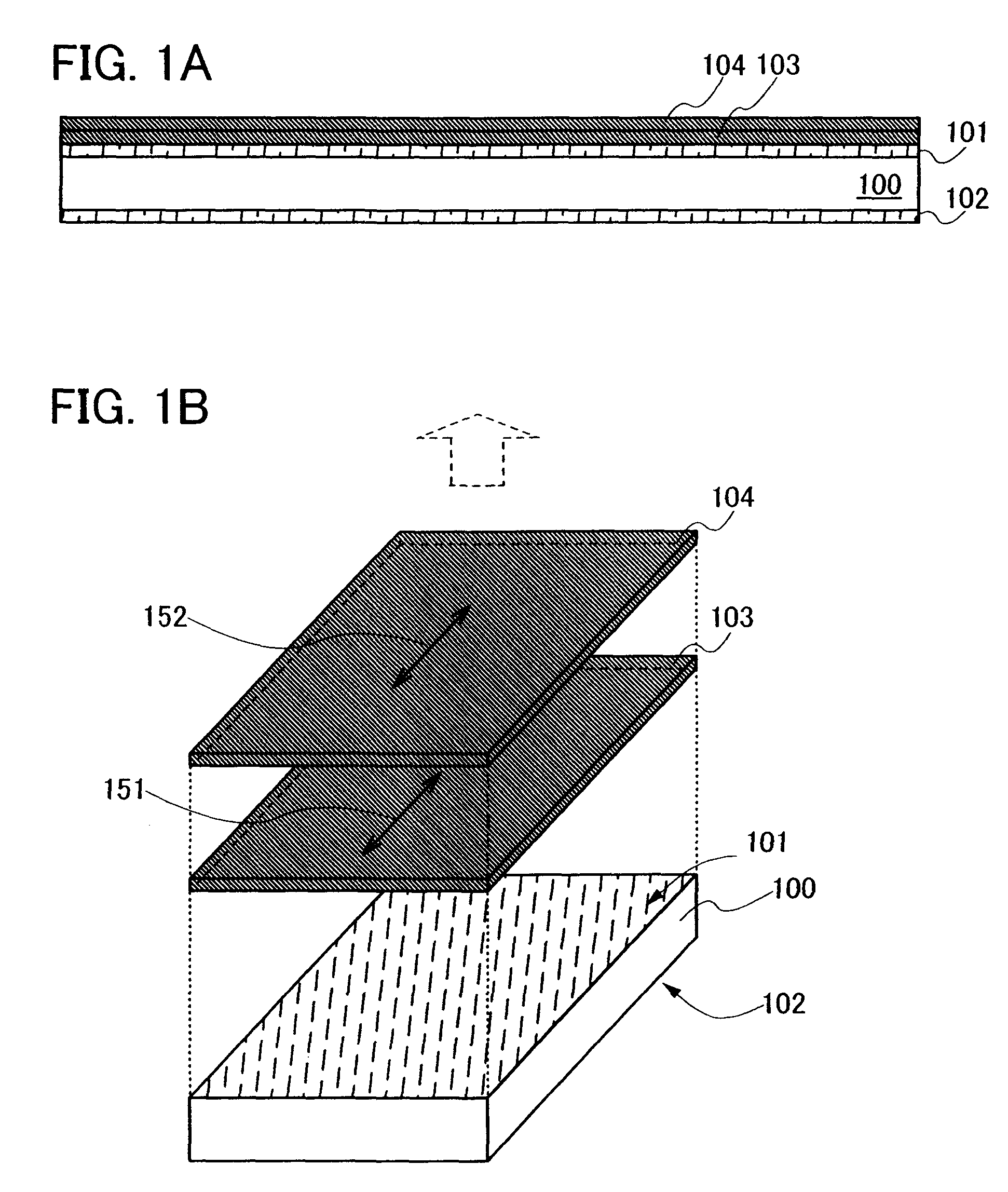
[0161]Embodiment Mode 1 will describe a conception of a display device of the present invention with reference to FIGS. 1A and 1B.
[0162]FIG. 1A is a cross-sectional view of a display device in which polarizers are stacked, and FIG. 1B is a perspective view thereof.
[0163]As shown in FIG. 1A, a display element 100 is interposed between a first substrate 101 and a second substrate 102 which are arranged to be opposite to each other.
[0164]Light-transmitting substrates can be used for the first substrate 101 and the second substrate 102. As such light-transmitting substrates, a glass substrate such as alumino borosilicate glass, barium borosilicate glass, a quartz substrate, or the like can be used. A substrate made from acrylic or plastic typified by polyethylene terephthalate (PET), polyethylene naphthalate (PEN), or polyethersulfone (PES) can be used for the light-transmitting substrates.
[0165]Polarizers are stacked on the outer side of the substrate 101, in other words, on the side w...
embodiment mode 2
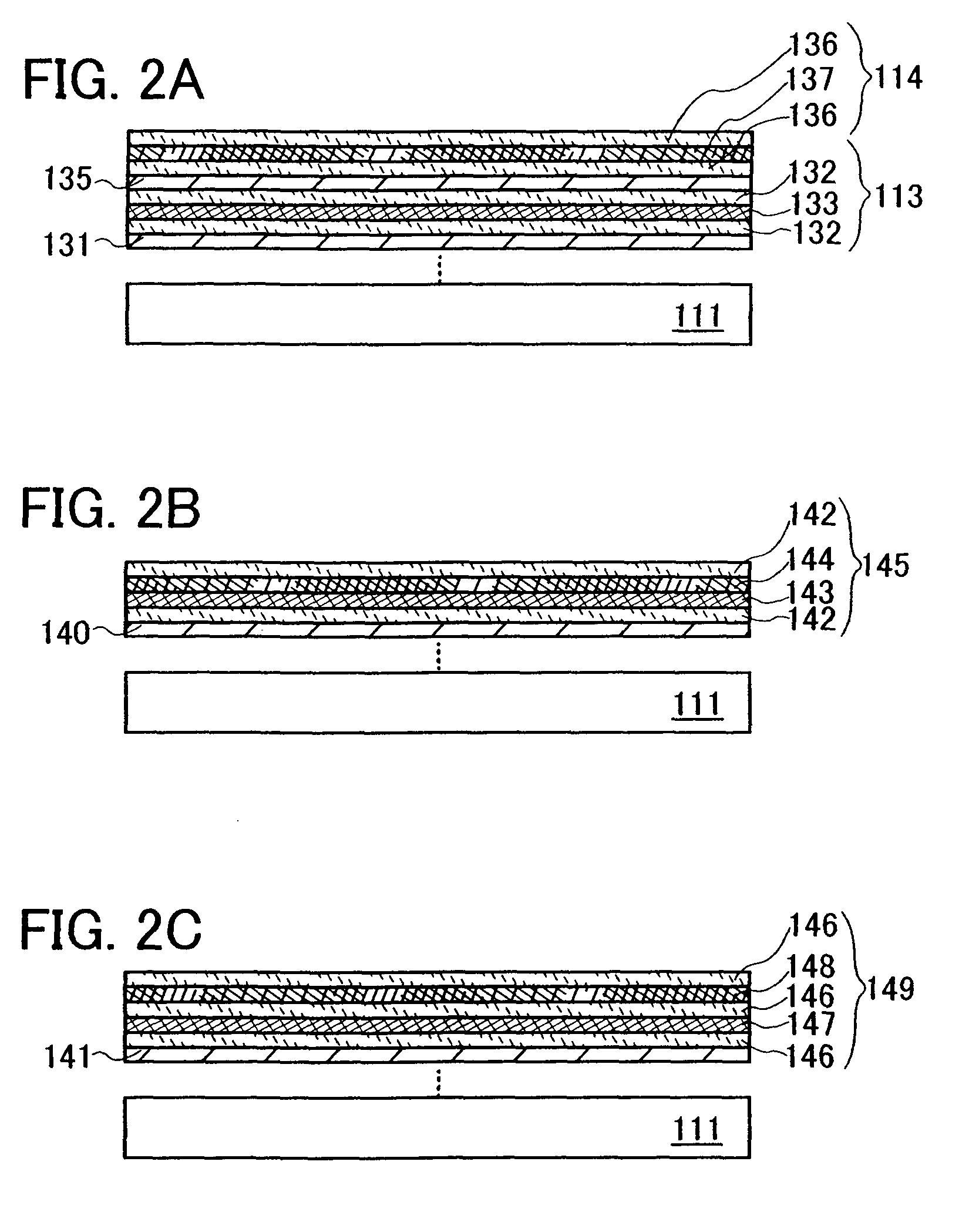
[0174]Embodiment Mode 2 will describe a structure in which polarizers are stacked with reference to FIGS. 2A to 2C.
[0175]FIG. 2A shows an example in which polarizing plates having one polarizing film are stacked as the stacked polarizers.
[0176]In FIG. 2A, each of the polarizing plates 113 and 114 is a linear polarizing plate, and can be formed from a known material with the following structure. For example, an adhesive layer 131, the polarizing plate 113 in which a protective film 132, a polarizing film 133, and another protective film 132 are sequentially stacked, an adhesive layer 135, and the polarizing plate 114 in which a protective film 136, a polarizing film 137, and another protective film 136 are stacked similarly to the polarizing plate 113, can be stacked from the substrate 111 side (FIG. 2A). As the protective films 132 and 136, TAC (triacetylcellulose) or the like can be used. As the polarizing films 133 and 137, a mixed layer including PVA (polyvinyl alcohol) and a dic...
embodiment mode 3
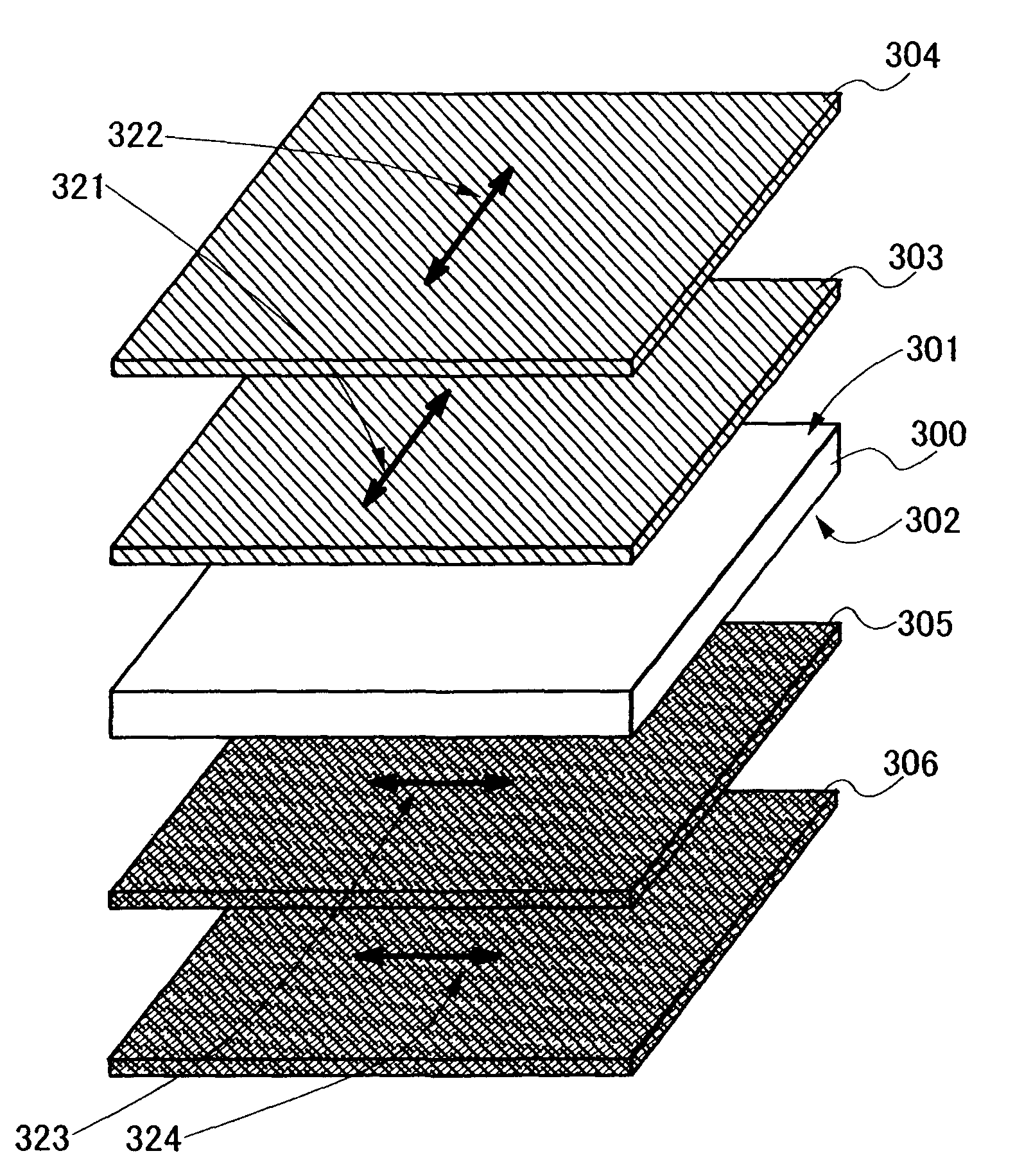
[0202]Embodiment Mode 3 will describe a concept of a display device of the present invention with reference to FIGS. 3A and 3B.
[0203]FIG. 3A is a cross sectional view of a display device in which a retardation plate and stacked polarizers are provided, and FIG. 3B is a perspective view of the display device.
[0204]As shown in FIG. 3A, a display element 200 is interposed between a first substrate 201 and a second substrate 202 which are opposite to each other.
[0205]Light-transmitting substrates can be used for the first substrate 201 and the second substrate 202. As such light-transmitting substrates, a similar material to the material of the substrate 101 described in Embodiment Mode 1 may be used.
[0206]On the outer side of the first substrate 201 and the second substrate 202, i.e., on the side which is not in contact with the display element 200 from the first substrate 201, a retardation plate 211, and polarizers 203 and 204 which are stacked are provided. Light is circularly polar...
PUM
 Abstract
Description
Claims
Application Information
 - Generate Ideas
- Intellectual Property
- Life Sciences
- Materials
- Tech Scout
- Unparalleled Data Quality
- Higher Quality Content
- 60% Fewer Hallucinations
Browse by: Latest US Patents, China's latest patents, Technical Efficacy Thesaurus, Application Domain, Technology Topic, Popular Technical Reports.
© 2025 PatSnap. All rights reserved.Legal|Privacy policy|Modern Slavery Act Transparency Statement|Sitemap|About US| Contact US: help@patsnap.com