Vehicle headlamp

a headlamp and headlamp technology, applied in the field of headlamps, can solve the problems of large power consumption, small power consumption of light emitting diodes, and large power consumption of light emitting diodes, and achieve the effect of reducing a number of parts and excellent assembly performan

Inactive Publication Date: 2007-08-09
KOITO MFG CO LTD
View PDF3 Cites 44 Cited by
  • Summary
  • Abstract
  • Description
  • Claims
  • Application Information

AI Technical Summary

Benefits of technology

[0011]One or more embodiments of the present invention provide a vehicle headlamp capable of achieving excellent assembling performance by reducing a number of parts.
[0026]That is, according to the invention, the first subunit and the second subunit commonly share the single lens and therefore, in comparison with a case of providing respectively separate lenses, a number of parts can be reduced and also spaces of attaching other attaching members of a lens holder and the like can be made common. Therefore, the first subunit and the second subunit can be arranged proximately to each other. Therefore, a space occupied by a total of the light source unit can be reduced and the light source unit can be downsized.
[0029]Further, according to the embodiments, the two light emitting elements are arranged on the same board. Therefore, in assembling, the two light emitting elements may be positioned to the single board and may be combined with other member and therefore, assembling performance can be promoted and accuracies of positioning the two light emitting portions can also be promoted by constituting a reference by the single board.

Problems solved by technology

Although a halogen bulb or a discharge bulb is a light source capable of ensuring a sufficient light amount for vehicular use, a problem that power consumption is large is posed.
A light emitting diode is generally small-sized and power consumption thereof is small.
Although high luminance formation of a light emitting diode has been promoted, in comparison with a halogen bulb or a discharge bulb, a luminance thereof is not sufficient yet, and a light amount capable of sufficiently ensuring optical recognizability cannot be irradiated to a front side by simply replacing a halogen bulb or a discharge bulb by a light emitting diode.
Further, the constitution is not preferable in view of cost.

Method used


Image

  • Vehicle headlamp
  • Vehicle headlamp
  • Vehicle headlamp

Examples


Embodiment Construction

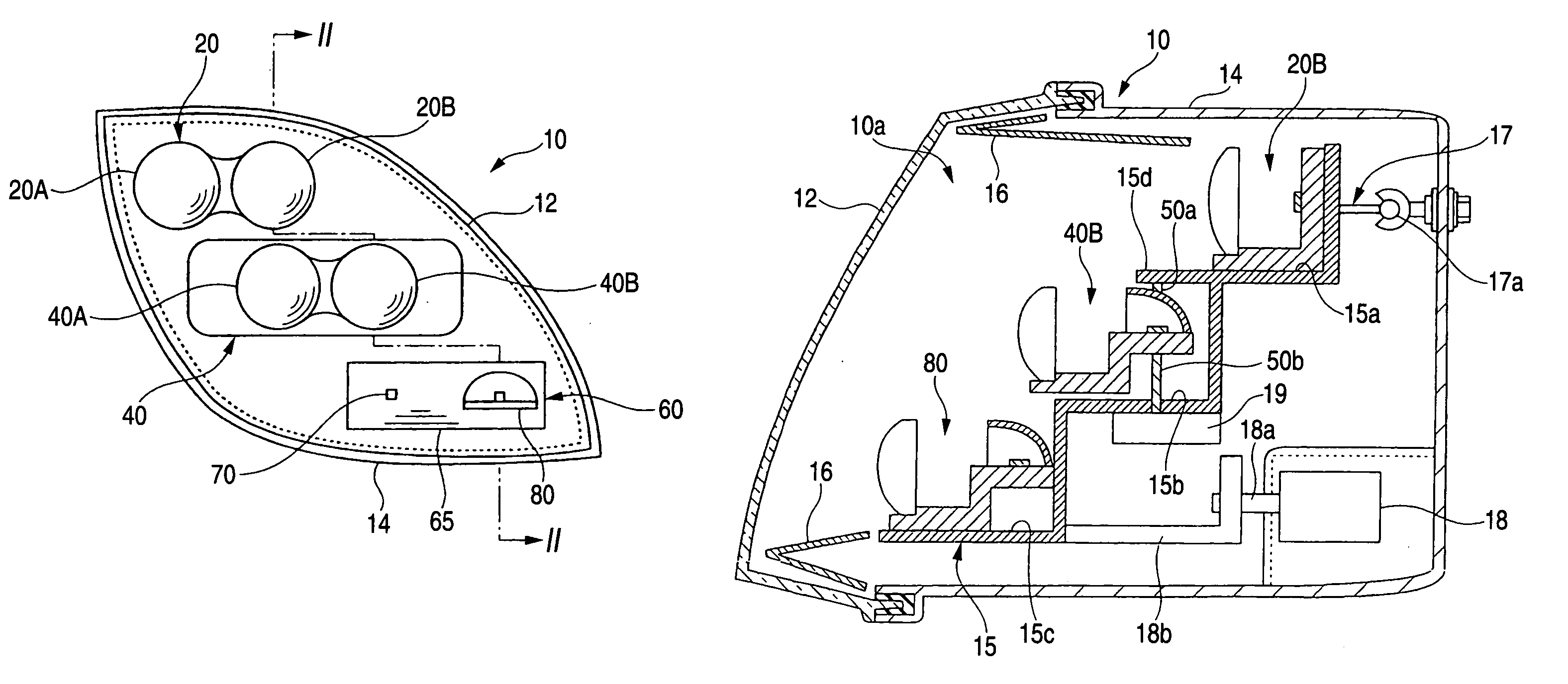
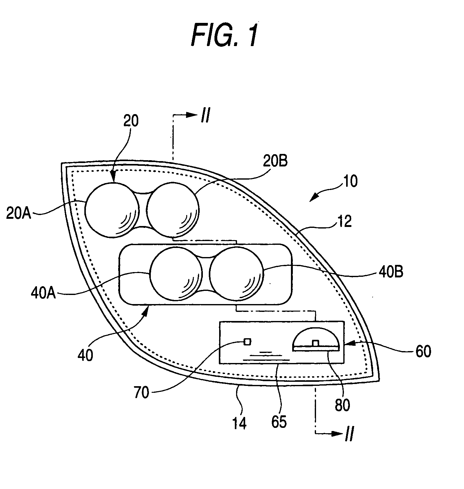
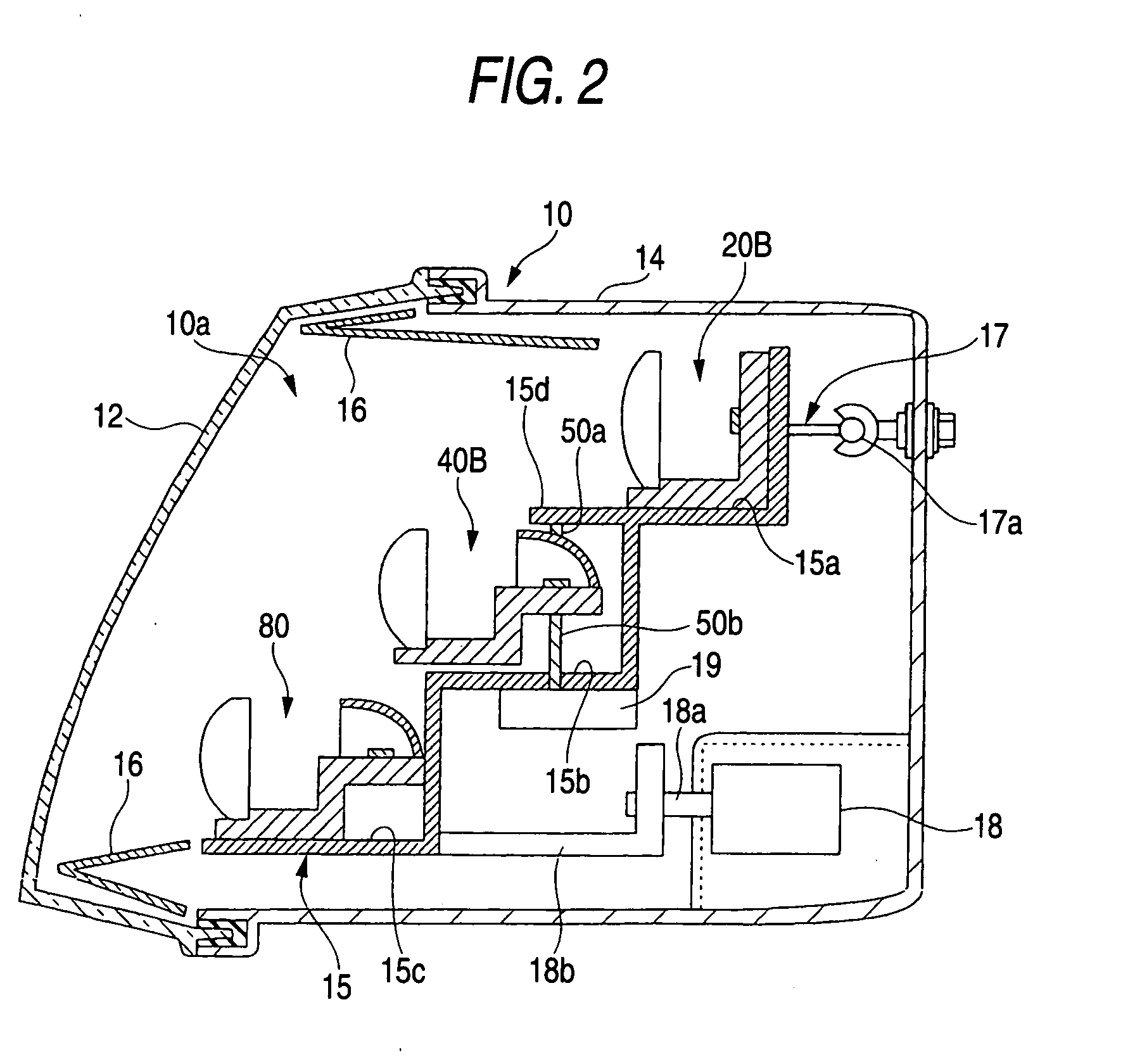
[0050]An explanation will be given of exemplary embodiments of a vehicle headlamp according to the invention in reference to the drawings as follows.

[0051]FIG. 1 is a front view showing a vehicle headlamp according to the embodiment of the invention. FIG. 2 is a sectional view taken along a line II-II of the vehicle headlamp. FIG. 3 is a vertical sectional view of a first subunit provided at an upper stage light source unit. FIG. 4 is a vertical sectional view of a third subunit provided at a middle stage light source unit. FIGS. 5(a) and 5(b) illustrate horizontal sectional views of the third subunit. FIG. 6 is a perspective view of a lower stage light source unit. FIG. 7 is a vertical sectional view showing a fifth subunit of the lower stage light source unit. FIG. 8 is a vertical sectional view showing a sixth subunit of the lower stage light source unit. FIG. 9 is a top view of the lower stage light source unit.

[0052]A vehicle headlamp 10 according to the embodiment is a headlam...


PUM


Abstract

A vehicle headlamp is provided with an upper stage light source unit, a middle stage light source unit, and a lower stage light source unit. The upper stage light source unit, the middle stage light source unit, and the lower stage light source unit are provided at a lamp body constituting a lamp member by way of a support member. A low beam light distribution pattern is formed on a front side of a vehicle by overlapping light from the respective light source units. The lower stage light source unit includes two subunits, the two subunits commonly share a single cylindrical lens.

Description

[0001]This application claims foreign priority from Japanese Patent Application No. 2006-030466, filed on Feb. 8, 2006, the entire contents of which are hereby incorporated by reference.BACKGROUND OF THE INVENTION[0002]1. Field of the Invention[0003]The present invention relates to a vehicle headlamp, particularly relates to a vehicle headlamp for forming a predetermined light distribution pattern by overlapping light emitted from a plurality of light sources.[0004]2. Related Art[0005]In a background art, as a vehicle headlamp (headlamp), it is general to use a halogen bulb or a discharge bulb as a light source and reflect light emitted from the light source to a front side by using a reflector or a projecting lens. Although a halogen bulb or a discharge bulb is a light source capable of ensuring a sufficient light amount for vehicular use, a problem that power consumption is large is posed.[0006]On the other hand, there is a high tendency of adopting a semiconductor light emitting ...

Claims


Application Information

Patent Timeline
Patent Type & Authority Applications(United States)
IPC IPC(8): B60Q1/00F21S8/10
CPCB60Q1/085B60Q2300/112B60Q2300/122B60Q2300/132B60Q2300/312F21Y2101/02B60Q2300/332B60Q2300/334F21S48/1154F21S48/1159F21S48/1163B60Q2300/314F21Y2115/10F21S41/143F21S41/148F21S41/153F21S41/155
Inventor NAGANAWA, MASAHITOTSUKAMOTO, MICHIO
Owner KOITO MFG CO LTD
Why Eureka
Try Eureka