Method and system for transmitter envelope delay calibration

a transmitter envelope and delay calibration technology, applied in the field of rf transmitters, can solve the problems of delay mismatch, inability to pass amplitude modulation without spectral regrowth,

Active Publication Date: 2007-08-09
III HLDG 3
View PDF4 Cites 112 Cited by
  • Summary
  • Abstract
  • Description
  • Claims
  • Application Information

AI Technical Summary

Problems solved by technology

These non-linear power amplifiers, however, cannot pass amplitude modulation without spec

Method used


Image

  • Method and system for transmitter envelope delay calibration
  • Method and system for transmitter envelope delay calibration
  • Method and system for transmitter envelope delay calibration

Examples


Embodiment Construction

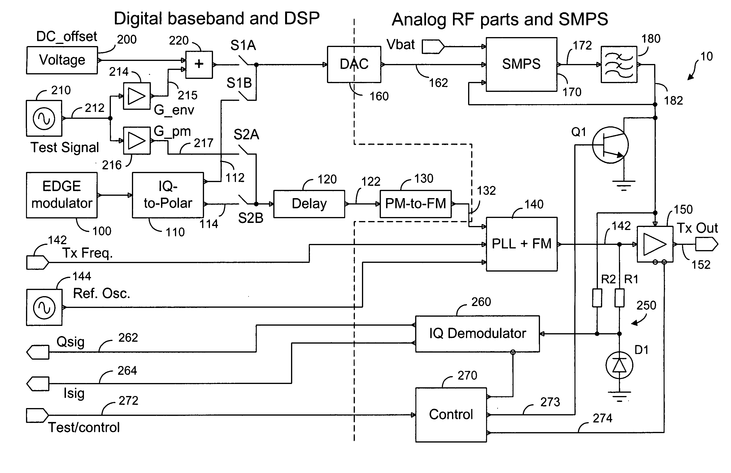
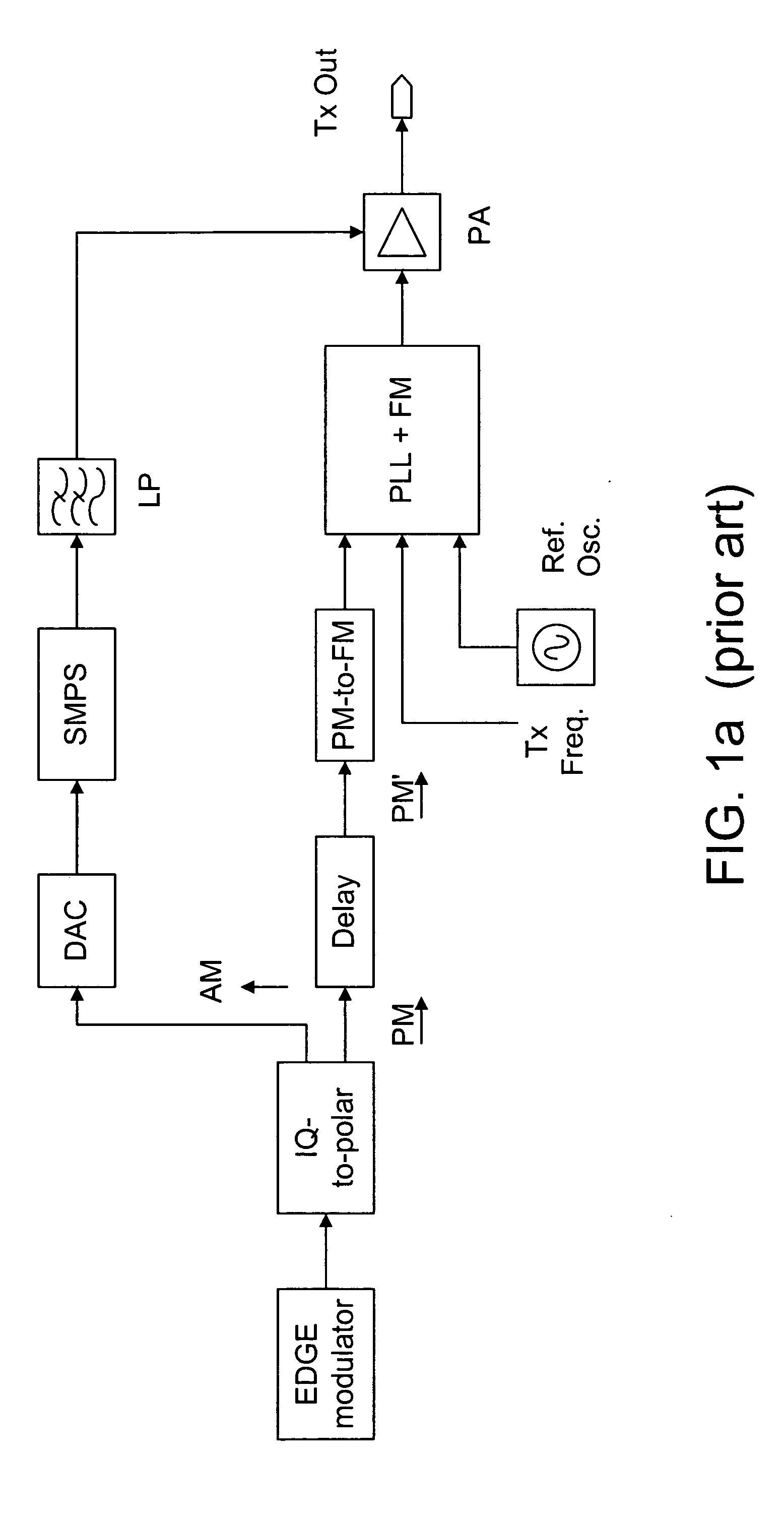
[0022] As shown in FIG. 1a, a delay block is disposed in the phase component path to compensate for the longer propagation delay in the envelope path. The present invention provides a method and system to determine the accurate delay compensation value for the delay block. An exemplary system for determining the delay compensation value for the delay block is shown in FIG. 2.

[0023] As shown in FIG. 2, an EDGE modulation module 100 is used to provide the I and Q digital baseband data as modulated by 8PSK to an IQ-to-Polar converter 110, where the EDGE modulation signal is separated into an AM component 112 and a PM component 114. The AM component 112 is conveyed in an envelope path to a digital-to-analog converter (DAC) 160 where the digital AM component is converted to an analog AM component 162. After being converted by a switch-mode power supply (SMPS) 170, the amplified AM component 172 is filtered by a low-pass filter 180 so that an envelope signal 182 indicative of the AM comp...


PUM


Abstract

A test signal comprising a periodic waveform, such as a triangular waveform and sawtooth waveform, is used for propagation delay matching in a transceiver front-end. The test signal is separately fed to the envelope path and the RF path. At the power amplifier stage, a phase modulator is used to obtain the envelope signal and the phase modulated RF signal for demodulation by an IQ demodulator. At the output end of the IQ demodulator, the I-signal is measured while the delay block is adjusted in order to vary the propagation delay. When the propagation delay matching is correct, the peak-to-peak value of the I-signal is a minimum. Preferably, during calibration using the test signal, the transmitter RF power amplifier is disabled so that no spurious signals will be sent. The transmitter can be an EDGE polar transmitter, a non-EDGE transmitter or a EER polar transmitter.

Description

FIELD OF THE INVENTION [0001] The present invention relates generally to a RF transmitter and, more particularly, to adjusting the path delay difference between the envelope path and the RF path in a polar transmitter. BACKGROUND OF THE INVENTION [0002] Conventionally, a direct upconversion transmitter has at least an I / Q modulator, an RF mixer, a filter and a power amplifier. The I / Q modulator is an efficient way to generate phase-modulated signals. It relies on two orthogonal signals, I (in-phase) and Q (quadrature), to produce a single complex waveform. In a direct upconversion transmitter, the I / Q modulator transforms the frequency spectrum of each orthogonal input signal to the RF carrier frequency. As such, two digital-to-analog (D / A) converters are needed to transform a digital baseband into an analog baseband. [0003] In recent years, other forms of transmitters have received attention from the RF R&D community: transmitters that use high efficiency, non-linear power amplifie...

Claims


Application Information

Patent Timeline
IPC IPC(8): H04L25/49H04L27/20
CPCH03C5/00H03F1/0205H03F1/0261H03F3/24H04L27/364H03F2200/336H03F2200/351H03F2200/504H04L27/361H03F2200/102H04B1/04
Inventor MATERO, JORMA
Owner III HLDG 3
Why Eureka
Try Eureka