Fluid dynamic bearing, spindle motor, disk drive, and manufacturing method of fluid dynamic bearing

Inactive Publication Date: 2007-08-09
NIDEC CORP
View PDF5 Cites 11 Cited by
  • Summary
  • Abstract
  • Description
  • Claims
  • Application Information

AI Technical Summary

Benefits of technology

[0016] However, in the fluid dynamic bearing according to the preferred embodiments of the present invention, the flat region is arranged at and along the outer peripheral edge of the thrust bearing surface. Therefore, a portion to be cut can be held over its entire peripheral length when punching is carried out. Accordingly, generation of burrs in the dynamic pressure generating grooves and deforming of the dynamic pressure generating grooves during punching can be prevented as compared with the conventional technique, and it is possible to prevent the lowering of the bearing performance and make the bearing performance more stable.

Problems solved by technology

However, the first dynamic pressure generating grooves are formed on the upper surface of the bearing housing in the intermediate form, and it is therefore difficult to hold the intermediate form at side surfaces and bottom surfaces of the first dynamic pressure generating grooves with jigs.
The burrs generated in radial outer portions of the first dynamic pressure generating grooves may interfere with the supply and circulation of the lubricating fluid and lower the bearing characteristics.
This pressing force may cause deformation of the first dynamic pressure generating groove, thus varying the bearing characteristics between products.

Method used


Image

  • Fluid dynamic bearing, spindle motor, disk drive, and manufacturing method of fluid dynamic bearing
  • Fluid dynamic bearing, spindle motor, disk drive, and manufacturing method of fluid dynamic bearing
  • Fluid dynamic bearing, spindle motor, disk drive, and manufacturing method of fluid dynamic bearing

Examples


first preferred embodiment

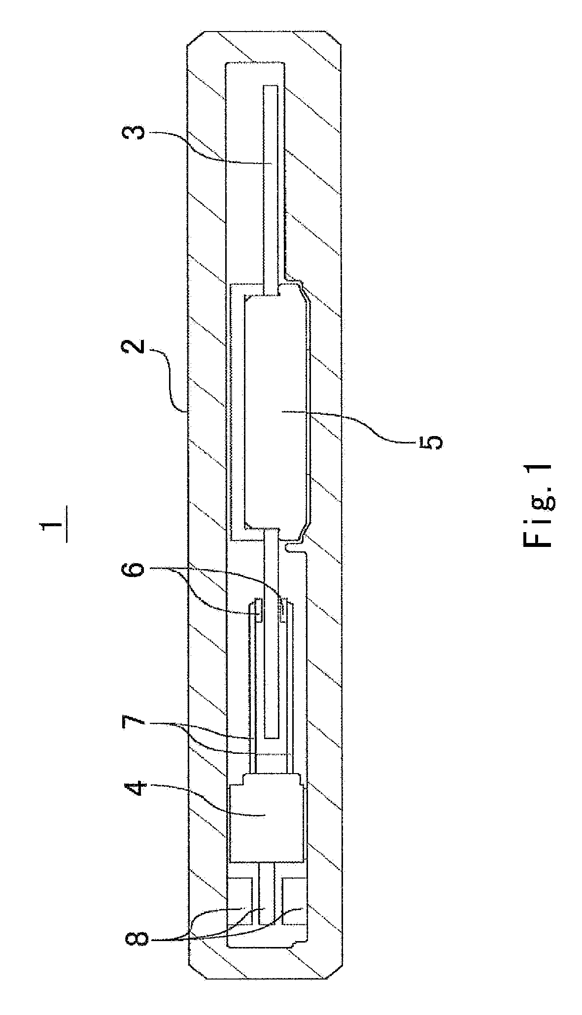
[0027]FIG. 1 is a vertical cross-sectional view of a disk drive 1 according to a first preferred embodiment of the present invention. The disk drive 1 is, for example, a hard disk drive with reduced size and height for rotating a small disk-shaped storage medium (hereinafter, simply referred to as a disk), e.g., a single one-inch disk.

[0028] The disk drive 1 includes a housing 2 which accommodates other components of the disk drive 1, such as a disk 3, a magnetic head moving portion 4, and a spindle motor 5 therein.

[0029] The disk 3 is a disk-shaped member having a magnetic recording layer formed of magnetic material. Information can be magnetically recorded on the disk 3. A one-inch disk, for example, can be used as the disk 3, or any other suitable size may be used.

[0030] The magnetic head moving portion 4 includes a pair of magnetic heads 6, a pair of arms 7, and actuators 8. The magnetic head moving portion 4 carries out at least one of reading and recording of information fr...

second preferred embodiment

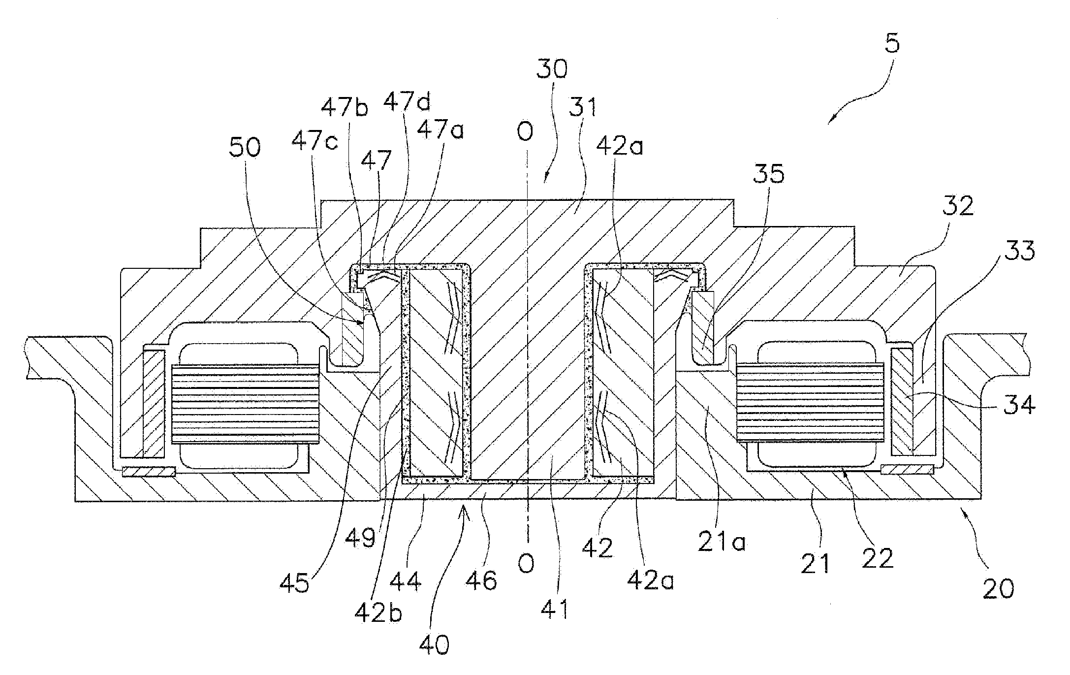
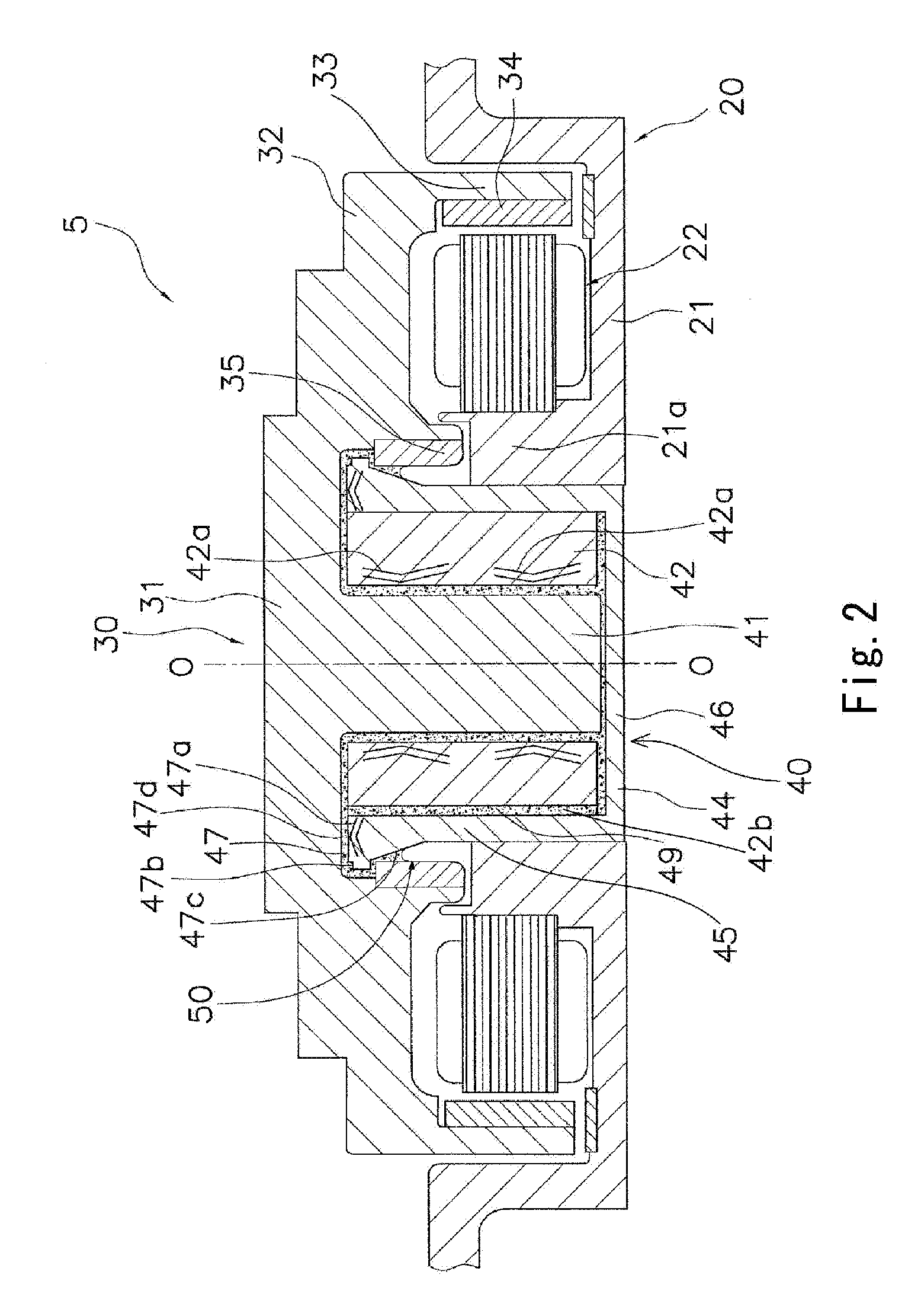
[0071] The bearing housing 44 and the sleeve 42 may be unitary and formed of a single component, although they are formed as separate components from each other in the first preferred embodiment. FIG. 5 is a vertical cross-sectional view of a spindle motor 105 according to a second preferred embodiment of the present invention. Differences between the present preferred embodiment and the first preferred embodiment are now described.

[0072] As shown in FIG. 5, a sleeve 142 of the spindle motor 105 includes a ring-shaped flange 147 at an axial upper end of the sleeve 142. The flange 147 has a plurality of first dynamic pressure generating grooves 147a and a flat region 147b formed on an axial upper surface thereof. The flat region 147b is ring-shaped. The spindle motor 105 of the present preferred embodiment operates in the same manner as the spindle motor of the first preferred embodiment and has the same effects as those obtained in the first preferred embodiment.

third preferred embodiment

[0073] The thrust dynamic bearing portion can be arranged on a lower side of a spindle motor in the axial direction, although the thrust dynamic bearing portion is arranged on an upper side in the first and second preferred embodiments. FIG. 6 is a vertical cross-sectional view of a spindle motor 205 according to a third preferred embodiment of the present invention. Differences between the present preferred embodiment and the first and second preferred embodiments are now described.

[0074] As shown in FIG. 6, a thrust plate 247 (serving as a thrust bearing surface), that is ring-shaped, is arranged at an axial lower end of a shaft 241 in the spindle motor 205. The thrust plate 247 is inserted and secured to the end of the shaft 241. On an axial lower surface of the thrust plate 247 are formed a plurality of first dynamic pressure generating grooves 247a and a flat region 247b. The flat region 247b is ring-shaped. The spindle motor 205 operates in the same manner as the spindle moto...


PUM


Abstract

A fluid dynamic bearing includes a sleeve, a shaft arranged inside the sleeve with a gap interposed therebetween, and a hollow cylindrical bearing housing having a closed end and an open end. The bearing housing is arranged outside the sleeve and has a flange having a thrust bearing surface. A plurality of dynamic pressure generating grooves are formed on the thrust bearing surface. A flat region surrounding the dynamic pressure generating grooves is formed on the thrust bearing surface at and along an outer peripheral edge of the thrust bearing surface.

Description

BACKGROUND OF THE INVENTION [0001] 1. Field of the Invention [0002] The present invention relates to a fluid dynamic bearing. More particularly, the present invention relates to a fluid dynamic bearing including a thrust dynamic bearing portion, and a spindle motor and a disk drive that include the same, and a fabrication method of the fluid dynamic bearing. [0003] 2. Description of the Related Art [0004] Disk drives such as hard disk drives include a spindle motor for rotating a disk-shaped storage medium (hereinafter, simply referred to as a disk). The spindle motor includes a base plate, a ring-shaped stator which is secured to the base plate and around which a stator coil is wound, a rotor accommodated inside the stator and having a rotor magnet, and a bearing for supporting the rotor in a rotatable manner relative to the base plate. A fluid dynamic bearing is used as the bearing of the spindle motor in order to achieve high-speed, low-vibration, and low-noise operation. [0005] ...

Claims


Application Information

Patent Timeline
IPC IPC(8): F16C32/06
CPCF16C17/107F16C2370/12F16C33/107
Inventor HADA, YASUAKI
Owner NIDEC CORP
Why Eureka
Try Eureka