Bearing structure

a technology of bearings and fixing parts, applied in the direction of bearing cooling, crankshafts, mechanical equipment, etc., can solve the problems of deteriorating bearing performance, insufficient shaft center adjustment function, and difficulty in firmly fixing or fixing miniature metal bearings to casings or housings, so as to improve lubricating performance, improve bearing performance, and stabilize the effect of shaft center adjustment performan

Inactive Publication Date: 2009-08-20
CALSONIC KANSEI CORP
View PDF5 Cites 2 Cited by
  • Summary
  • Abstract
  • Description
  • Claims
  • Application Information

AI Technical Summary

Benefits of technology

[0006]It is therefore an object of the present invention to provide a bearing structure which is capable of improving the bearing performance, stabilizing the shaft-center-adjustment performance, and improving the lubricating performance.

Problems solved by technology

For this reason, it is difficult to firmly secure or fix a miniature metal bearing to a casing or a housing.
In addition, projections and depressions (i.e. asperity) appear on a bearing surface depending on processing accuracy, and this might result in deterioration of bearing performance.
Furthermore, as shown in JP,59-185962, in a case where the outer periphery of the metal bearing is formed in a spherical shape to allow a shaft-center-adjustment function, if the asperity appears on the bearing surface by forming the ventilation passages at the outer periphery of the metal bearing, there is a possibility that the shaft-center-adjustment function will not function adequately.
Therefore, due to the increase of the surface area, in a case where the metal bearing is a bearing that is impregnated with a lubricant, an outflow quantity of the lubricant impregnated in the metal bearing rises when the metal bearing is heated, and this causes deterioration in lubricating performance.
On the other hand, due to the decrease of the volume of the metal bearing, an impregnation quantity of the lubricant that is impregnated in the entire metal bearing lowers, and this may cause deterioration in lubricating performance as well.
In addition, in a case where a ring-shaped movement restriction member that serves for positioning in an axial direction is provided, if the ventilation passages are formed in the metal bearing, a contact state of the metal bearing with the movement restriction member is not constant throughout the circumference of metal bearing, namely that the metal bearing does not uniformly contact or touch the movement restriction member throughout the circumference of metal bearing.
As a consequence, when the metal bearing slides for performing the shaft-center-adjustment, a smooth sliding movement of the metal bearing is not achieved, and there is a risk that desired shaft-center-adjustment performance will not be obtained.

Method used


Image

  • Bearing structure
  • Bearing structure
  • Bearing structure

Examples


embodiment 1

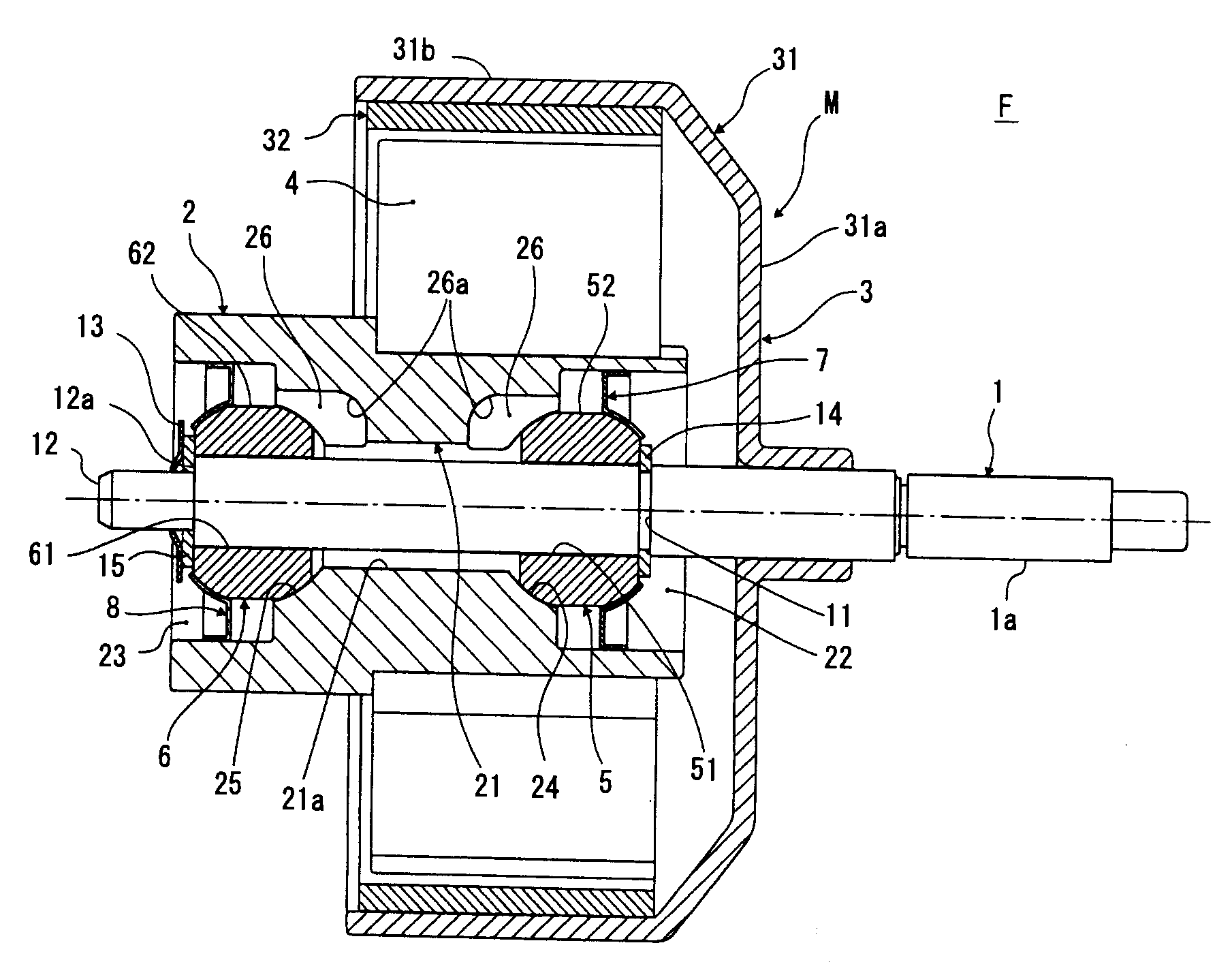
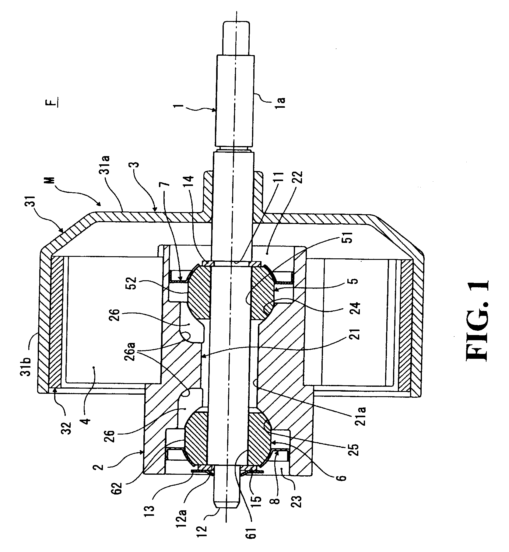
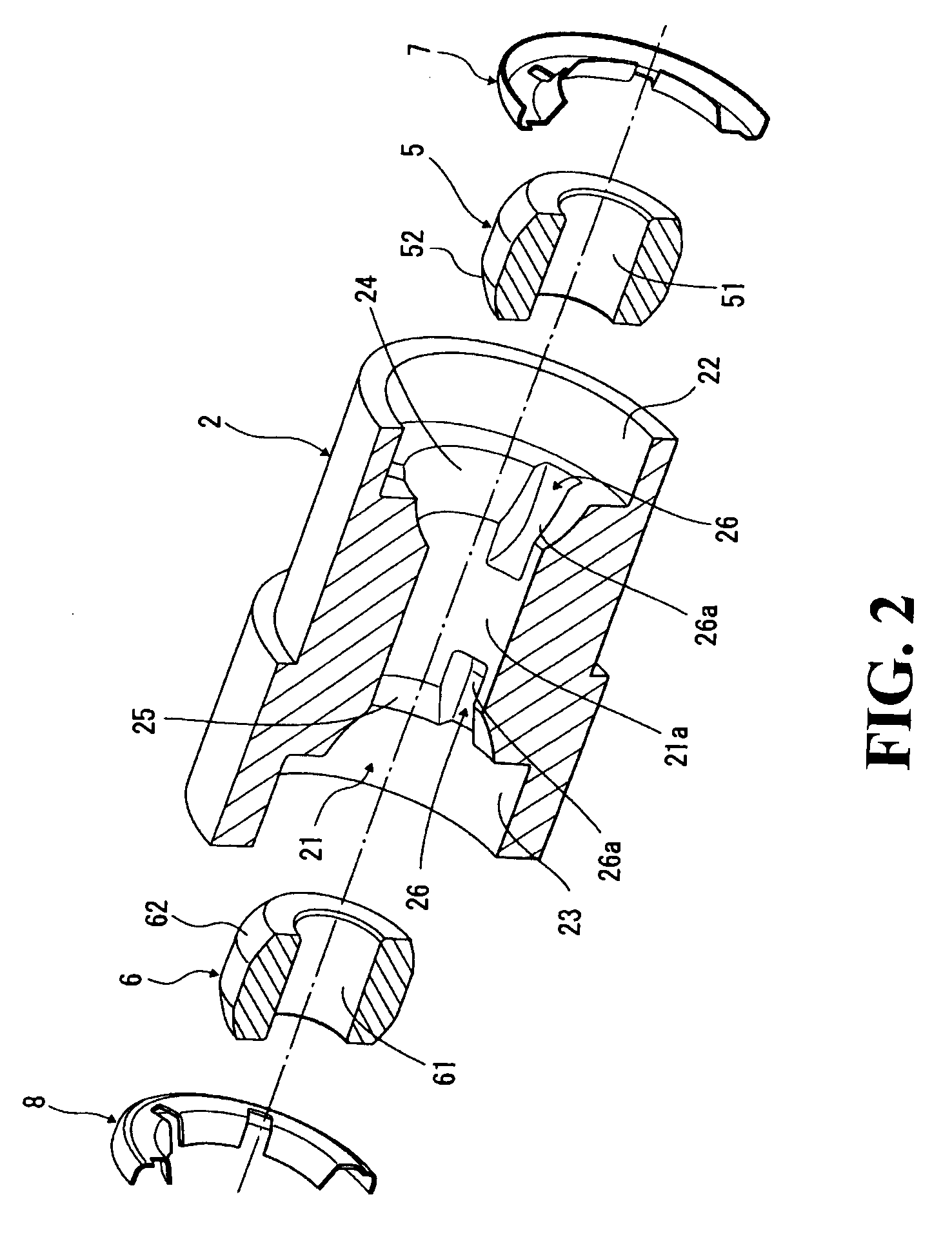
[0020]An electric fan unit employing a bearing structure of the present invention, has a housing (2) having a bore (21) that penetrates the housing (2); a rotation shaft (1) inserted into the bore (21); annular first and second metal bearings (5, 6) which are provided apart from each other in an axial direction in the bore (21) and rotatably support the rotation shaft (1); and a ventilation passage (26) which is provided in the housing (2) and bypasses at least one of the first and second metal bearings (5, 6), and through which a closed area sandwiched between the both first and second metal bearings (5, 6) inside the bore (21) communicates with an outside area.

[0021]More specifically, as shown in FIGS. 1 and 2, the bearing structure of the embodiment 1 is applied to a motor M of the electric fan unit F, and the electric fan unit F includes the motor M that rotates a fan (not shown). The motor M has a rotation shaft 1, a housing 2, a rotor 3, a stator 4, a first metal bearing 5, a ...


PUM


Abstract

A bearing structure includes a housing having a bore that penetrates the housing, a rotation shaft inserted into the bore, an annular first metal bearing and an annular second metal bearing, which are provided apart from each other in an axial direction in the bore and rotatably support the rotation shaft, and a ventilation passage provided in the housing. The ventilation passage is formed on the housing-side contact surfaces which are formed on an inner surface of the housing, and bypasses at least one of the first metal bearing and the second metal bearing. Through ventilation passage, a closed area sandwiched between the both first metal bearing and second metal bearing inside the bore communicates with an outside area.

Description

BACKGROUND OF THE INVENTION[0001]The present invention relates to a bearing structure employing a metal bearing which is used in rotating machinery such as a motor.[0002]A bearing structure, in which a pair of metal bearings are provided apart from each other in an axial direction of a rotating shaft and support the rotating shaft, has been known. In a case of such bearing structure, there is a problem producing an ill effect such as an increase in mechanical resistance, caused by heat generation when the shaft rotates, and an increase in noise. For this problem, for instance, Published utility model application Nos. JP,59-185962, U(1984) and JP,60-192654, U(1985) disclose techniques, in which ventilation passages or grooves (channels) are formed at an outer or an inner periphery of the metal bearing and cooling air is provided between the both metal bearings, to resolve the problem caused by the heat generation.SUMMARY OF THE INVENTION[0003]In the above related art techniques discl...

Claims


Application Information

Patent Timeline
Patent Type & Authority Applications(United States)
IPC IPC(8): F16C37/00
CPCH02K5/20F16C23/043H02K7/085H02K5/207
Inventor SANO, NARIHITOOHIRA, SHIGENORIYAMADA, KAZUNORIKAWARAI, HIROMIKAWACHI, KATSUYOSHI
Owner CALSONIC KANSEI CORP
Why Eureka
Try Eureka